A floating net vortex elimination method used before the water inlet

A water inlet and floating net technology, applied in the field of floating net vortex elimination, can solve the problems of difficult to predict the vertical axis vortex phenomenon of the water inlet, unable to guarantee effective control and elimination, large amount of engineering, etc., to achieve strong practical scope and use value, Conducive to popularization and application, the effect of small amount of engineering

Inactive Publication Date: 2017-12-15
SICHUAN UNIV
View PDF1 Cites 0 Cited by
  • Summary
  • Abstract
  • Description
  • Claims
  • Application Information

AI Technical Summary

Problems solved by technology

However, as far as the current research level is concerned, it is still an unsolved problem to predict the vertical axis vortex in front of the water inlet.
Due to the scale effect of the vortex, the vertical axis vortex was successfully eliminated in the model test, which cannot guarantee that it can be effectively controlled and eliminated in actual engineering
The actual problem is: before the construction and operation of the project, it is difficult to predict whether there will be a vertical axis vortex phenomenon in front of the water inlet, which water level and flow conditions it may occur in, etc.
However, the realization of this design requires an underwater structure with a certain strength. If it is modified after completion, the amount of work will be large, the cost will be high, and it will be difficult to realize

Method used


Image

  • A floating net vortex elimination method used before the water inlet
  • A floating net vortex elimination method used before the water inlet

Examples


Embodiment 1

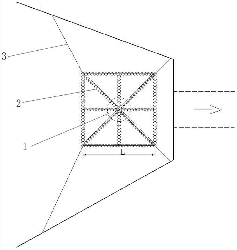
[0024] figure 2 It is a schematic diagram of the structure of the floating net of the present invention, which is a "meter"-shaped net structure, with pull ropes on the edge, and the inside and frame materials of the floating net 2 are connected by swimming lane lines.

[0025] This embodiment adopts this floating net vortex elimination method, which is intended to be used in the water inlet of a diversion tunnel in a certain project. The water inlet section of the diversion tunnel used is a city gate type with a width of 2.80m and a height of 3.60m, wherein: the height of the straight wall 2.80m, 0.80m sag height, 857.50m elevation of the water inlet floor; followed by a 262.45m long city gate tunnel with a diameter of 2.80m×3.60m (width×height).

[0026] A kind of vortex elimination method for the floating net before the water inlet described in this embodiment, the specific steps are as follows:

[0027] (1) The outdoor model test observation shows that when the water lev...

Embodiment 2

[0033] Another embodiment of the present invention is to replace the "meter" font floating net 2 with a regular hexagonal floating net, by the formula L=(3.0~5.0)D 涡max It can be calculated that the value range of the side length L of the floating net is 9.0cm~15.0cm, and the side length L=9.0cm of the floating net is taken in the present embodiment, wherein D 涡max is the maximum diameter of the vertical axis vortex, other operating steps and experimental conditions are the same as in Example 1.


PUM


Abstract

The invention relates to a floating net vortex eliminating method applied in front of a water inlet. The method comprises the following steps: (1) firstly, a water level with stronger and stable serial inspiration vortex in front of the water inlet is observed through visual inspection; and meanwhile, the position and the diameter size of the vertical shaft vortex in front of the water inlet are determined; (2) the diameter size of the vertical shaft vortex is determined through visual inspection to produce a floating net with an edge length L=(3.0-5.0) D vortex max; (3) the vortex eliminating mounting position of the floating net, produced in the step (2), on the water surface in front of the water inlet is determined according to the position, of the vertical shaft vortex in front of the water inlet, determined through visual inspection in the step (1); and (4) the floating net produced in the step (2) is fixedly mounted in the position of the water surface with the vertical shaft vortex in front of the water inlet determined in the step (3). The method has the following prominent characteristics: after the vertical shaft vortex is discovered in front of the water inlet in engineering operation, the vortex eliminating floating net is produced according to actual conditions and mounted according to the vortex generation position, so that the pertinence is higher.

Description

technical field [0001] The invention belongs to the technical field of water conservancy engineering, in particular to a vortex elimination method for a floating net before a water inlet. Background technique [0002] The vertical axis vortex in front of the water inlet of hydraulic engineering buildings, that is, the free water surface vortex, sometimes occurs in front of the water inlets of hydropower station diversion pipes, diversion tunnels, spillways, and large water pumps. The existence of the vertical axis vortex will deteriorate the flow state of the water inlet, reduce the flow capacity, reduce the efficiency of the unit, intensify the pulsation of the water flow, entrain the floating objects and block or damage the trash rack, etc., which will bring serious damage to the water conservancy project buildings and electromechanical equipment. harm and cause huge economic losses. [0003] The research shows that the induction of the vertical axis vortex is mainly affe...

Claims


Application Information

Patent Timeline
Patent Type & Authority Patents(China)
IPC IPC(8): E02B8/06
CPCE02B8/06
Inventor 陈云良赵琼王波杨华杨秀玲
Owner SICHUAN UNIV
Why Eureka
Try Eureka