A miniature regenerative diffused uniform combustion device with a tapered combustion chamber

A uniform combustion and combustion chamber technology, applied in the direction of combustion chambers, continuous combustion chambers, combustion methods, etc., can solve the problems of high-power burner flow rate and blowout, short residence time of reaction gas, insufficient local mixed combustion, etc. , to achieve the effects of prolonging the gas movement path, uniform flame and temperature distribution, and reducing the difficulty of ignition

Inactive Publication Date: 2018-02-27
CHONGQING UNIV
View PDF6 Cites 0 Cited by
  • Summary
  • Abstract
  • Description
  • Claims
  • Application Information

AI Technical Summary

Problems solved by technology

At the same time, since the micro-scale burner is not simply scaled down on the scale of the traditional burner, it will generate many new problems and challenges: first, the heat dissipation is serious due to the relative increase of the surface area; second, due to the size of the burner Too small, the residence time of the reaction gas is short, the combustion is not sufficient and the combustion efficiency is low; 3. Many existing micro burners use a single air inlet, which is easy to form a temperature field distribution caused by excessive local temperature along the air inlet direction Uneven and insufficient partial mixed combustion seriously affect the combustion efficiency; 4. The existing burner has a small air intake surface, which causes the intake air flow rate to be too high under large flow, resulting in blown out phenomenon; while high-power burners require There is a contradiction between the large flow rate and the blow-out phenomenon, and the small air intake surface of the existing burner cannot solve the contradiction between the flow rate and the blow-out phenomenon in the high-power burner

Method used


Image

  • A miniature regenerative diffused uniform combustion device with a tapered combustion chamber
  • A miniature regenerative diffused uniform combustion device with a tapered combustion chamber
  • A miniature regenerative diffused uniform combustion device with a tapered combustion chamber

Examples


Embodiment Construction

[0028] The present invention will be described in further detail below in conjunction with the accompanying drawings and specific embodiments.

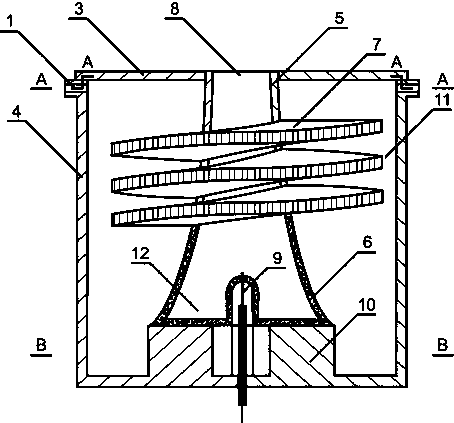
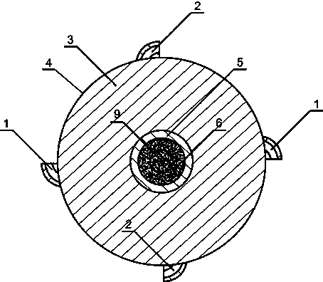
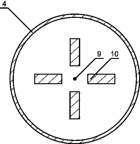
[0029] Such as figure 1 , figure 2 with image 3 As shown, a miniature regenerative diffuse uniform combustion device with a tapered combustion chamber includes an ignition device 9 , an outer sleeve 4 , an inner sleeve 5 and an upper panel 3 . The inner sleeve 5 is located in the outer sleeve 4, and the inner sleeve 5 and the outer sleeve 4 are coaxially arranged. The outer wall of the inner sleeve 5 adopts a "three-stage" different structure, and the inner sleeve 5 is a combustion chamber 12. A preheating and premixing chamber 11 is formed between the inner sleeve 5 and the outer sleeve 4 to provide space for sufficient premixing and preheating of the gas. The bottom end of the outer sleeve 4 is provided with a sealing plate, and the upper panel 3 is arranged on the top end of the outer sleeve 4 and sealed with the outer sleeve ...


PUM


Abstract

The invention provides a miniature heat regeneration diffusion type uniform combustion device with a combustion room shrunk gradually. The miniature heat regeneration diffusion type uniform combustion device comprises an ignition device, an outer sleeve, an inner sleeve and an upper panel. The inner sleeve is located in the outer sleeve. The combustion room is arranged in the inner sleeve. A preheating and premixing cavity is formed between the inner sleeve and the outer sleeve. The upper panel is arranged at the top end of the outer sleeve. A porous bottom plate is arranged at the lower end of the inner sleeve. The circumferential wall of the lower portion of the inner sleeve is a porous wall. An upper end opening of the inner sleeve serves as an exhaust opening. The combustion room communicates with the preheating and premixing cavity through the porous wall and the porous bottom plate. A plurality of air inlets and gas inlets are evenly distributed in the top end of the side wall of the outer sleeve in the circumferential direction. The combustion room of the miniature heat regeneration diffusion type uniform combustion device is in a reversely-buckled cylindrical inwards-concave horn shape so that fuel in the combustion room can be diffused, and inner combustion and temperature field distribution can be more uniform. According to the miniature heat regeneration diffusion type uniform combustion device, smoke waste heat is utilized, meanwhile, a porous material is adopted for multi-face air feeding, combustion is strengthened, a temperature field is more uniform, and therefore the power of the device is improved.

Description

technical field [0001] The invention relates to the field of micro gas turbines, in particular to a miniature regenerative dispersion uniform combustion device with a combustion chamber tapering (smoke acceleration). This device accelerates the flue gas while improving its own combustion efficiency, provides high-temperature flue gas with higher kinetic energy for the turbine part of the gas turbine, and further increases the power of the gas turbine. Background technique [0002] Micro-scale combustion is proposed with the development of MEMS (micro-electromechanical system) technology, and its combustion is usually below 1cm 3 occurs within the volume. The power generation principle of micro-scale combustion is: micro-scale burners produce high-temperature flue gas to drive heat engines to generate power, or obtain electricity through direct conversion of thermoelectric materials and generate electricity through photoelectric materials. The application fields involve micr...

Claims


Application Information

Patent Timeline
Patent Type & Authority Patents(China)
IPC IPC(8): F23R3/42
CPCF23R3/42
Inventor 闫云飞吴刚娥尹昊文张力翟越冯帅蒲舸杨仲卿唐强陈艳容冉景煜丁林
Owner CHONGQING UNIV
Why Eureka
Try Eureka