Oil and gas separator with adjustable flow and parallel multi-branches

一种油气分离器、多支路的技术,应用在机器/发动机、用于弹性流体的泵送装置的部件、旋转活塞式/摆动活塞式的泵部件等方向,能够解决无法满足动力用螺杆压缩机试验系统宽量程高效率低成本等问题,达到除油效果良好、有利于分离、提高除油效率的效果

Active Publication Date: 2016-08-03
HEFEI GENERAL MACHINERY RES INST
View PDF7 Cites 4 Cited by
  • Summary
  • Abstract
  • Description
  • Claims
  • Application Information

AI Technical Summary

Problems solved by technology

[0004] The current horizontal oil separator usually uses only filtration, gravity or simple centrifugal force to separate oil and gas. Most of the targets are compressor equipment with a single specification or a small flow range. Single use of traditional oil and gas separation equipment can no longer meet the power requirements. Design requirements for wide range, high efficiency and low cost of screw compressor test system

Method used


Image

  • Oil and gas separator with adjustable flow and parallel multi-branches
  • Oil and gas separator with adjustable flow and parallel multi-branches
  • Oil and gas separator with adjustable flow and parallel multi-branches

Examples


Embodiment Construction

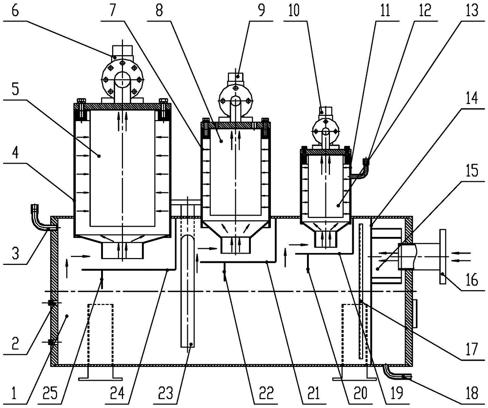
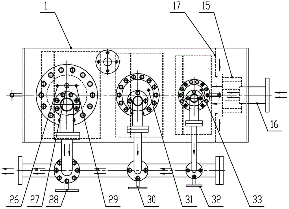
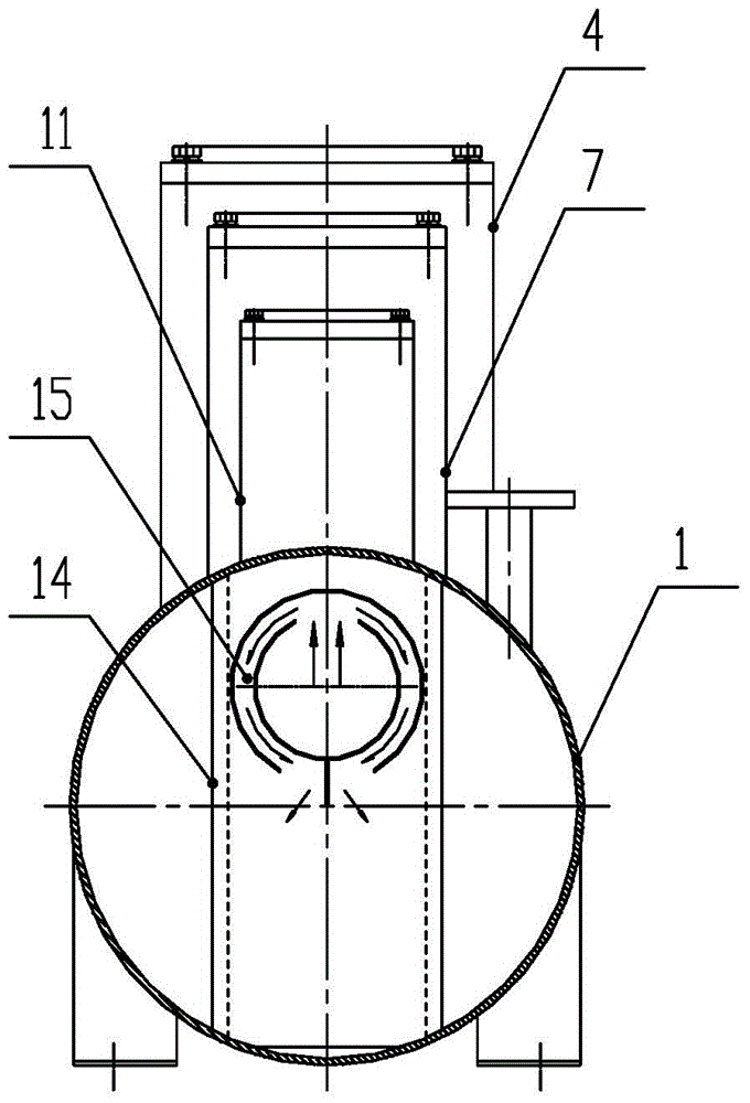
[0043] The present invention will be further explained below in conjunction with the accompanying drawings. Figure 1~4 The arrow in is the flow direction of the oil-gas mixture.

[0044] Such as Figure 1~4 As shown, the cylinder 1 of the present oil and gas separator is provided with a feed pipe 16 for conveying a mixture of oil and gas, a circulating lubricating oil outlet pipe 23 connected with an oil pump, and an exhaust pipe system for discharging gaseous separated materials. A centrifugal degreasing unit 15, a labyrinth degreasing unit, a three-row filter degreasing unit, and an exhaust piping are sequentially arranged between the body 1 from the feed pipe 16 to the exhaust pipe system.

[0045] Such as figure 1 , 2 As shown, one end of the feed pipe 16 is inserted into the first centrifugal degreasing pipe 15a of the centrifugal degreasing unit 15. The oil and gas mixture enters the first centrifugal degreasing pipe 15a from the feed pipe 16, and the first centrifugal degr...


PUM


Abstract

The invention relates to an oil and gas separator with adjustable flow and parallel multi-branches. A feeding pipe transporting the gas-oil mixture, an oil outlet pipe connected with an oil pump and an exhaust pipe system discharging gas separation material are disposed on a cylindrical shell. The cylindrical shell is provided with a centrifuging oil-removing unit, a labyrinth-type oil-removing unit and at least two columns of filtering oil-removing units in order, and the outlets of the filtering oil-removing units are connected with the exhaust pipe system. A plurality of filtering oil-removing units have different sizes. The exhaust pipe system comprises a plurality of exhaust pipes corresponding with the filtering oil-removing units one-to-one, and each exhaust pipe is provided with a minimal pressure valve and a valve used for opening and closing the pipeline at the position near the outlet of each filtering oil-removing unit. The oil and gas separator integrates the effect of filtration, gravity and centrifugal force, and the technical requirement of the test system with wide range, high efficiency and low cost can be solved by means of different combination mode of parallel-type controllable exhaust pipe system, so that the functions of cyclic utilization of the lubricating oil and performance test of multi-standard compressor can be realized efficiently and reliably.

Description

[0001] This application is a divisional application for an invention patent whose application date is May 23, 2014, the application number is "201410222957.0", and the invention name is "a wide-range horizontal high-efficiency oil-gas separator for screw compressor test systems". Technical field [0002] The invention relates to a parallel multi-branch flow adjustable oil-gas separator. Background technique [0003] The power oil-injected screw compressor needs a lot of lubricating oil to lubricate the mechanical running parts of the compressor, seal the compressed gas, and take away the heat generated in the compressor at the same time. In this process, the lubricating oil After being mixed with the suction gas and compressed, it leaves the compressor in the form of an oil-gas mixture. At this time, a wide-range and high-efficiency oil-gas separator is required to separate these lubricating oils from the oil-gas mixture. On the one hand, it is to ensure that it faces multiple spec...

Claims


Application Information

Patent Timeline
Patent Type & Authority Applications(China)
IPC IPC(8): F04C29/02
CPCF04C29/026
Inventor 于洋张成彦何明王树胜高相家方燚张志恒
Owner HEFEI GENERAL MACHINERY RES INST
Why Eureka
Try Eureka