Dehumidifying house

A technology for wet room and house, applied in the field of optimization technology of dehumidification room, can solve the problems of difficult evaporation and poor drying effect, etc.

Active Publication Date: 2016-05-04
李耀强
View PDF3 Cites 15 Cited by
  • Summary
  • Abstract
  • Description
  • Claims
  • Application Information

AI Technical Summary

Problems solved by technology

For rooms with high humidity requirements, air conditioners are usually used to dehumidify. The advantage is that the structure is simple. The disadvantage is that the air conditioner will reduce the indoor temperature during the dehumidification process. As the indoor temperature decreases, the moisture in the items will not easily evaporate. Therefore, the air conditioner has a better dehumidification effect on humid air, but if the indoor temperature is low and the moisture content of the item is high, the air conditioner will have a poor drying effect on the item

Method used


Image

  • Dehumidifying house

Examples


Embodiment Construction

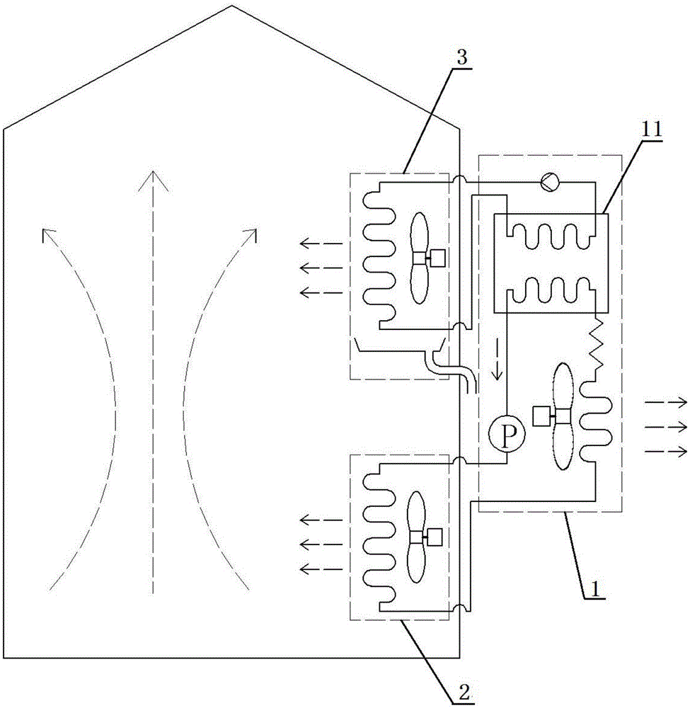
[0014] Such as figure 1 As shown, a dehumidification room mainly includes a house and a dryer, and the dryer mainly includes a host 1 , a heater 2 and a condenser 3 .

[0015] The main engine is installed outside the house, and the heating machine and condensing machine are installed inside the house.

[0016] The main engine mainly includes a compressor, a main engine fan, a second condenser, a throttle valve and a cold storage box 11.

[0017] The heating machine 2 mainly includes a heating fan and a first condenser.

[0018] The condenser 3 mainly includes a condensing fan, an evaporator and a water receiving tray, the water receiving tray is installed below the evaporator, and the bottom wall of the water receiving tray is provided with a drainpipe to discharge the water in the water receiving tray to the outside of the house.

[0019] The main machine and the heating machine are connected through pipelines for transporting refrigerant.

[0020] The dryer is also provid...


PUM


Abstract

The invention relates to a dehumidifying house. The dehumidifying house mainly comprises a house and a drier. A heating fan inhales air in the house, and the air is blown over a first condenser, so that water in articles enters the air to become hot humid air; a coolant flows back into a second condenser and a throttle in a main machine to be further cooled, and then the cooled coolant enters a third condenser in a cold storage box; the coolant in the third condenser flows back to a compressor to be squeezed into a high-temperature high-pressure coolant, and then the high-temperature high-pressure coolant flows back to a heating machine, so that cold storage fluid in the cold storage box is kept within a preset temperature range; a fourth condenser soaked in the cold storage fluid in the cold storage box is affected by the cold storage fluid to be cooled; the cooled coolant in the fourth condenser is conveyed to an evaporator through a high-pressure pump; a condensing fan inhales the indoor hot humid air which is blown to the evaporator, water in the hot humid air is separated out to downwards drop into a water pan under the evaporator, dry cold air is blown out from a condensing machine, and after the temperature of a cold drive of the evaporator rises, the dry cold air flows back to the fourth condenser, and then is cooled by the cold storage fluid to flow to the evaporator.

Description

technical field [0001] The invention relates to a dehumidification room, which belongs to the optimization technology of the dehumidification room. Background technique [0002] Some houses have higher requirements on humidity, such as rooms used to store valuables such as tea, calligraphy and paintings. For rooms with high humidity requirements, air conditioners are usually used to dehumidify. The advantage is that the structure is simple. The disadvantage is that the air conditioner will reduce the indoor temperature during the dehumidification process. As the indoor temperature decreases, the moisture in the items will not easily evaporate. Therefore, the air conditioner has a better dehumidifying effect on humid air, but if the indoor temperature is low and the moisture content of the item is high, the air conditioner will have a poor drying effect on the item. [0003] Therefore, it is necessary to find a way to better evaporate the moisture in the article for drying. ...

Claims


Application Information

Patent Timeline
Patent Type & Authority Applications(China)
IPC IPC(8): F26B9/02F26B21/04
CPCF25B6/04F25B7/00F26B9/02F26B21/001F26B21/04F26B25/00F26B2200/20
Inventor 刘毓玉唐桂英张宇
Owner 李耀强
Why Eureka
Try Eureka