A method for detecting expansion rate of oil well cement

A technology for oil well cement and detection methods, applied in the direction of material thermal expansion coefficient, etc., can solve problems such as unreasonable structural design, high material cost, production safety accidents, etc., to improve measurement accuracy and accuracy, reduce test data errors, and guarantee The effect of production safety

Active Publication Date: 2018-12-25
JIAHUA SPECIAL CEMENT
View PDF9 Cites 0 Cited by
  • Summary
  • Abstract
  • Description
  • Claims
  • Application Information

AI Technical Summary

Problems solved by technology

The pavement cement concrete expansion coefficient testing device used in this detection method has an unreasonable structural design. First, it can only detect the expansion rate of cement stone at a curing temperature of 10-50 ° C, that is, the expansion rate of cement concrete for pavement, and cannot detect more. Expansion rate of cement stone under high ambient temperature; second, it is necessary to embed a temperature detector in the cement concrete test piece, which is difficult to recycle and reuse, and the material cost is high; third, the concrete test piece is fixed in the water tank and cannot be moved. During the test age, the displacement sensor cannot be reused
However, the ambient temperature of oil well cement varies greatly, and the properties of the expansion components of cement vary greatly at different temperatures. Using this device to test the expansion rate of oil well cement, there are large errors in the obtained data, which cannot provide information for oil well cement on site. Objective data reference makes it easy to form an annular gap between the oil well cement sheath and the formation, resulting in gas channeling and production safety accidents

Method used


Image

  • A method for detecting expansion rate of oil well cement
  • A method for detecting expansion rate of oil well cement
  • A method for detecting expansion rate of oil well cement

Examples


Embodiment 1

[0033] A method for detecting the expansion rate of oil well cement, comprising a pulping step, a mold loading step, and a maintenance and demoulding step, and also includes an initial measurement step, an age measurement step, and an expansion rate calculation step. The pulping step refers to a stirring cup Put it on the base of the agitator, mix the slurry with a water-cement ratio of 0.44, and stir evenly to obtain the slurry; the mold loading step refers to pouring the cement slurry into the test mold and mixing it evenly, and scraping off the upper part of the test mold with a scraper Excessive mud is covered with a test mold cover plate; the maintenance and demoulding step refers to putting the trial mold in the curing box, and demoulding after curing to obtain a cement test block; the initial measurement step refers to putting the mold after demoulding Mark the direction of the cement test block, and then put it into the measuring device that has been calibrated to zero,...

Embodiment 2

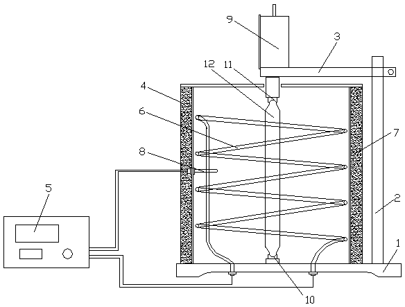
[0038] see figure 1 , a method for detecting the expansion rate of oil well cement, comprising a pulping step, a mold loading step, and a maintenance and demoulding step, and also includes an initial measurement step, an age measurement step, and an expansion rate calculation step, and the slurrying step refers to stirring The cup is placed on the base of the agitator, and the slurry is mixed with a water-cement ratio of 0.44, and the slurry is evenly stirred; the mold loading step refers to pouring the cement slurry into the test mold and mixing it evenly, and scraping off the test mold with a scraper. The excessive mud on the upper part is covered with a test mold cover plate; the curing and demoulding step refers to putting the trial mold in the curing box, and demoulding after curing to obtain a cement test block; the initial measurement step refers to putting the demoulding The direction of the final cement test block is marked, and then placed in the measuring device tha...

Embodiment 3

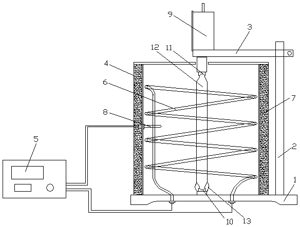
[0046] see figure 2 , a method for detecting the expansion rate of oil well cement, comprising a pulping step, a mold loading step, and a maintenance and demoulding step, and also includes an initial measurement step, an age measurement step, and an expansion rate calculation step, and the slurrying step refers to stirring The cup is placed on the base of the agitator, and the slurry is mixed with a water-cement ratio of 0.44, and the slurry is evenly stirred; the mold loading step refers to pouring the cement slurry into the test mold and mixing it evenly, and scraping off the test mold with a scraper. The excessive mud on the upper part is covered with a test mold cover plate; the curing and demoulding step refers to putting the trial mold in the curing box, and demoulding after curing to obtain a cement test block; the initial measurement step refers to putting the demoulding The direction of the final cement test block is marked, and then placed in the measuring device th...


PUM


Abstract

The invention discloses a method for detecting the oil-well cement expansion rate, and belongs to the technical field of cement preparation. The method comprises the steps of slurrying, mould filling and curing and demoulding. The method is characterized by further comprising the steps of initial measurement, age period measurement and expansion rate calculation, wherein the curing and demoulding step comprises the process that a cement test block is put into a curing box, and demoulding is conducted after curing is conducted; the initial measurement step comprises the process that the direction of the cement test block subjected to demoulding is marked, then the cement test block is put into a measuring device subjected to zero correction, and the initial length L<0> of the cement test block is measured; the age period measurement step comprises the processes that the cement test block subjected to initial measurement is put into the curing box to be cured continuously, and the length L<x> of the corresponding age period is measured after the corresponding age period is achieved; the expansion rate calculation step comprises the process that the expansion rate is calculated according to the formula shown in the description, wherein 250 represents the effective length of the cement test block. According to the method for detecting the oil-well cement expansion rate, the expansion rate of the cement test block can be tested at different environmental temperatures, the testing data error can be reduced, and the measurement precision and accuracy of the expansion rate of the cement test block can be improved.

Description

technical field [0001] The invention relates to the technical field of cement preparation, in particular to a method for detecting the expansion rate of oil well cement. Background technique [0002] In the cementing process of oil and gas wells, gas channeling is a frequently encountered technical problem. Current research shows that there are several factors that lead to gas channeling. During the solidification process of cement slurry, due to the drop of liquid column pressure, shrinkage of cement stone, water loss of cement slurry, etc., an annular gap is formed between the cement sheath and the formation. Under formation pressure, oil and gas move upward along the cracks to other formations or wellheads. Especially in high-pressure wells and natural gas wells, the problem of gas channeling is more prominent, which not only seriously affects the production of oil and gas resources, pollutes other formations, and may even cause serious production safety accidents. In o...

Claims


Application Information

Patent Timeline
Patent Type & Authority Patents(China)
IPC IPC(8): G01N25/16
CPCG01N25/16
Inventor 张凌志阳运霞曾雪玲古安林
Owner JIAHUA SPECIAL CEMENT
Why Eureka
Try Eureka