
Thermoelectricity module group generation performance test platform

A thermoelectric module and test platform technology, which is applied in the direction of single semiconductor device testing, measuring electricity, measuring devices, etc., can solve the problems that are not involved in the structural design of the test system, the influence of the power generation performance of the thermoelectric module, etc., and achieve simple structure and convenient assembly Effect

Inactive Publication Date: 2016-05-04
ZHEJIANG UNIV
View PDF9 Cites 8 Cited by
  • Summary
  • Abstract
  • Description
  • Claims
  • Application Information

AI Technical Summary

Problems solved by technology

[0005] According to the relevant patents, Tsinghua University applied for the patent "thermoelectric performance test system of thermoelectric generator" in 2006 (patent application number: 200610011549.6). It is composed of heat sink unit, data acquisition and data processing unit, but it does not involve the structural design of the test system; Nanjing University of Aeronautics and Astronautics applied for a patent in 2013 "A system and method for testing the thermoelectric conversion performance of temperature difference materials" (patent application No. : 201310186572.9), this patent introduces the functional framework of the test system, which is composed of an electric heating unit, a thermoelectric power generation device unit, a circulating cooling unit, and a data acquisition unit. However, this patent does not involve the structural design of the test system, nor does it involve the monitoring function of the installation pressure of the thermoelectric power generation device. In the actual application process, the temperature difference between the hot and cold ends of the thermoelectric power generation device and the installation pressure have an impact on the power generation performance of the thermoelectric module. great influence

Method used


Image

  • Thermoelectricity module group generation performance test platform
  • Thermoelectricity module group generation performance test platform
  • Thermoelectricity module group generation performance test platform

Examples


Embodiment Construction

[0027] The present invention will be further described below in conjunction with the accompanying drawings and embodiments.

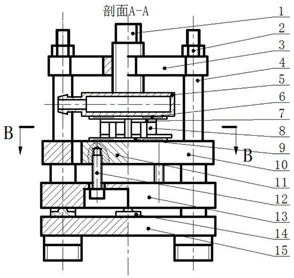
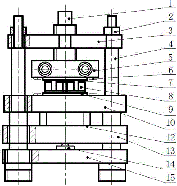
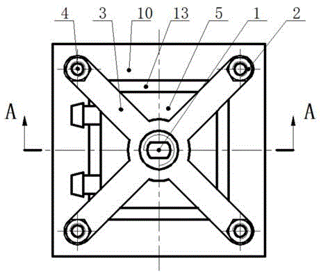
[0028] figure 1 , figure 2 , image 3 , Figure 4 As shown, as shown, the present invention includes a compression rod 1, a compression nut 2, a compression rod support block 3, a stepped support shaft 4, a water cooling block 5, a patch thermocouple 6, a conductive electrode 7, a thermoelectric block 8, ceramic Sheet 9, protective fence 10, electric heating platform 11, screws 12, heating platform support plate 13, pressure sensor 14 and support base plate 15. Compression module composed of pressure rod 1 and pressure rod support block 3, thermoelectric module composed of ceramic sheet 9, conductive electrode 7 and thermoelectric block 8, temperature monitoring module composed of chip thermocouple 6, and pressure sensor 14 A pressure monitoring module, a support module composed of a ladder support shaft 4 , a protective fence 10 , screws 12 , a he...


PUM


Abstract

The present invention discloses a thermoelectricity module group generation performance test platform. The thermoelectricity module group generation performance test platform comprises a gland nut, a pressure bar, a pressure bar support block, a step support shaft, a water cooling block, a paster thermocouple, a conductive electrode, a thermoelectricity block body, a ceramic chip, a protection fence, an electric heating platform, a screw, a heating platform support plate, a pressure sensor and a support base plate. The thermoelectricity module group generation performance test platform is able to heat the lower end of a thermoelectricity module group and control the heating end to heat temperature, perform water-cooling cooling of the upper end of the thermoelectricity module group, and compress the thermoelectricity module group to ensure that the electric heating platform and the thermoelectricity module group fully contact with the water cooling block to allow the upper end and the lower end of the thermoelectricity module group to form a stable temperature difference and generate an electromotive force. The thermoelectricity module group generation performance test platform is able to accurately test number values of the internal resistance, the output voltage, the current and the output power of a thermoelectricity module group in the conditions of different temperature differences, different external applied pressures and different external loads, and has an important guidance meaning for the manufacture technology optimization and the usage environment of the thermoelectricity module group such as usage temperature range, the installation pressure and the external load.

Description

technical field [0001] The invention relates to a testing platform, in particular to a testing platform for generating performance of a thermoelectric module. Background technique [0002] In the existing energy system, there is a large amount of low-grade energy, and there is a lot of waste heat in power plants, steel plants, vehicle exhaust, solar panels and other environments. Thermoelectric generator is an all-solid-state energy device that directly converts thermal energy into electrical energy by using thermoelectric power generation materials. It has the advantages of no noise, no wear, small size, long life, safety and no pollution, so it has great advantages in waste heat utilization. potential. [0003] The thermoelectric module is the core component of the thermoelectric generator that converts heat energy into electrical energy. It consists of P-type thermoelectric arms, N-type thermoelectric arms, conductive electrodes and ceramic sheets. When working, the h...

Claims


Application Information

Patent Timeline
Patent Type & Authority Applications(China)
IPC IPC(8): G01R31/26
CPCG01R31/2601
Inventor 梅德庆谌礼群王辉李佳碧
Owner ZHEJIANG UNIV
Learn More