Method for improving distance measurement precision of responder

A technology of distance measurement accuracy and transponder, which is applied in the field of improving the range measurement accuracy of transponders. It can solve the problems of reduced design reliability, impossibility, and increased power consumption, and achieve the effect of reducing clock jitter and improving accuracy.

Inactive Publication Date: 2016-05-04
10TH RES INST OF CETC
View PDF3 Cites 5 Cited by
  • Summary
  • Abstract
  • Description
  • Claims
  • Application Information

AI Technical Summary

Problems solved by technology

The implementation process is implemented inside the FPGA, the fractional part will be discarded, and the continuous accumulation of DDS will cause residual errors, resulting in errors in the generated code sending clock, which will eventually lead to inaccurate downlink frame synchronization trailing edge pulses
[0007] At present, there are mainly three methods to reduce the residual error: first, set the system clock to an integer multiple of the code sending clock. This method makes the clock design of the transponder very limited and basically impossible to realize; second, to increase the system clock, Taking this method will lead to problems such as reduced design reliability and increased power consumption; the third increase in frequency control word accumulator DDS digits, taking this method will lead to problems such as increased design resources, and the latter two methods will only produce the same The extension of the distance jump time does not fundamentally solve the problem

Method used


Image

  • Method for improving distance measurement precision of responder
  • Method for improving distance measurement precision of responder
  • Method for improving distance measurement precision of responder

Examples


Embodiment Construction

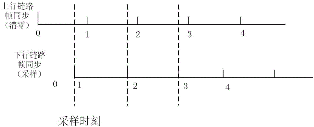
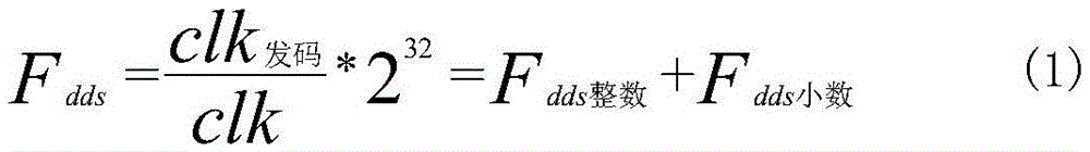
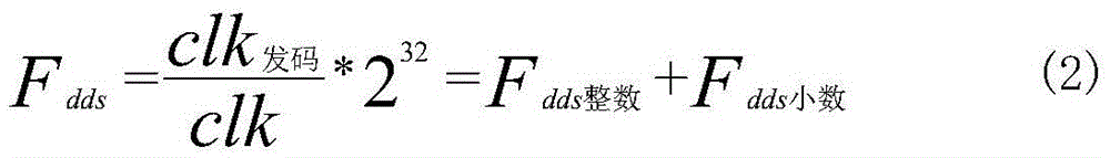
[0015] see figure 1 . According to the present invention, in the non-coherent mode, after receiving the uplink signal, the transponder extracts the frame synchronization information of the uplink through despreading, demodulation, and frame synchronization processing, and then uses the downlink frame synchronization trailing edge pulse to compare the uplink signal. Sampling, and reframing the sampled values ​​and sending them to the ground station using the downlink. The ground station measures the distance by calculating the time delay between sending frame synchronization and receiving frame synchronization; in the FPGA chip of the transponder hardware platform Program to realize the following compensation function, use the system clock of the transponder as the modulation clock of the downlink, use the 32-bit frequency control word accumulator DDS to generate the code-transmitting clock, and use the code-transmitting clock to generate the downlink frame synchronization trai...


PUM


Abstract

The invention provides a method for improving distance measurement precision of a responder and aims to provide a simple and reliable method for improving downlink frame synchronization trailing edge pulse precision. According to the method, in a noncoherent mode, after an uplink signal is received by the responder, the uplink frame synchronization information is extracted after de-spreading, demodulation frame synchronization processing, an uplink frame synchronization signal is sampled by utilizing the downlink frame synchronization trailing edge pulse, the sampling value after re-framing is sent to a ground station through a downlink, and distance measurement is carried out by the ground station through calculating time delay between sending frame synchronization and receiving frame synchronization. The method for improving distance measurement precision of the responder is advantaged in that the compensation function is realized through programming in an FPGA chip of a responder hardware platform, a system clock of the responder is used as a modulation clock of the downlink, a 32-bit frequency control word accumulator DDS is utilized to generate a code sending clock, and the code sending clock is utilized to generate the downlink frame synchronization trailing edge pulse.

Description

technical field [0001] The invention relates to a realization method for improving the ranging accuracy of a transponder in a non-coherent mode. Background technique [0002] In the non-coherent mode of the current mainstream measurement and control system, the outer ballistic measurement system needs to obtain high-precision ranging data without a high-precision ranging transponder that works together. Realize high-precision ranging and positioning. In the ranging system, the errors introduced by the transponder mainly include the zero-value offset error of the transponder itself, the zero-value measurement error introduced by the measurement, and the zero-value variation error caused by the environmental state change. Transponder zero-value offset error and zero-value measurement error will be directly introduced into the system accuracy, but both can reduce the amount of errors introduced by these two factors by improving the transponder performance and measurement accur...

Claims


Application Information

Patent Timeline
Patent Type & Authority Applications(China)
IPC IPC(8): G01S11/02
CPCG01S11/02
Inventor 李召飞陈霞
Owner 10TH RES INST OF CETC
Why Eureka
Try Eureka