Oiling system of capacitor

A capacitor and oil filling tank technology, applied in the direction of drying/dipping machine, etc., can solve the problems of waste, complicated pipelines and lines, easy to run, drip and leak, etc., and achieve the effects of convenient operation, convenient oil return and simple structure

Active Publication Date: 2016-05-04
宁波海融电器有限公司
View PDF13 Cites 4 Cited by
  • Summary
  • Abstract
  • Description
  • Claims
  • Application Information

AI Technical Summary

Problems solved by technology

[0003] But even so, the following defects still exist in the mass production of capacitors: (1) During mass production, many capacitors often enter the vacuum tank at the same time for vacuum drying, oil filling and impregnation. At this time, multiple capacitors will be placed on the flat car and divided into several columns, because each column of capacitors is composed of many capacitors, in order to facilitate loading and unloading, the oiling tank corresponding to each column of capacitors is composed of a plurality of short oiling tanks, and the multiple short oiling tanks are arranged in a row relative to each other. Located above the column of capacitors, in order to realize automatic oil filling, a liquid level sensor and a corresponding solenoid valve are installed in each short oil filling tank to control the liquid level in each short oil filling tank
And these short oil tanks must enter and leave the vacuum tank at the same time as the capacitor. At this time, the multiple liquid level gauges need to be designed as a lifting structure, or the electrical signal lead-out wires of the liquid level gauges are very long, but no matter which one is used structure, such multiple liquid level gauges and multiple solenoid valves will cause the disadvantages of complicated pipelines and circuits
(2) Especially after the oil is filled, it is very difficult to recover the oil in each short oil filling tank
It can be treated in this way, the waste is serious, and it is easy to leak, leak and pollute the environment

Method used


Image

  • Oiling system of capacitor
  • Oiling system of capacitor
  • Oiling system of capacitor

Examples


Embodiment Construction

[0019] The present invention will be further described in detail below in conjunction with the accompanying drawings and embodiments.

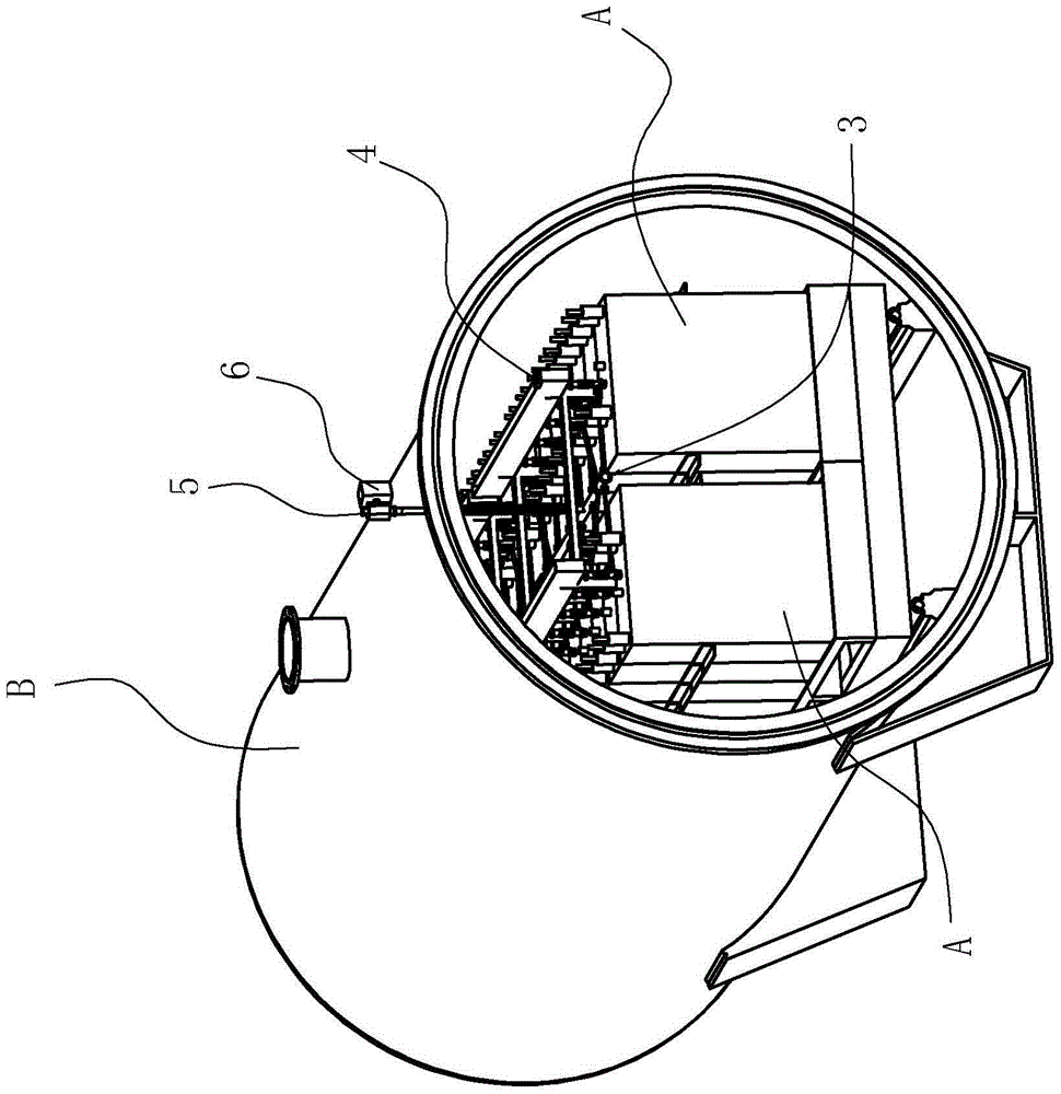
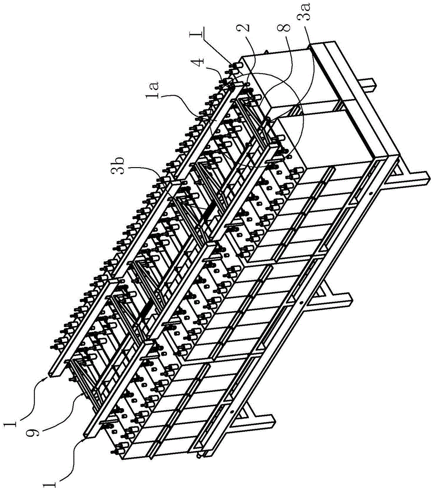
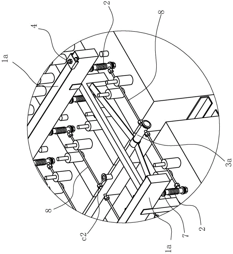
[0020] Such as Figure 1 to Figure 5 As shown, the capacitor oiling system of this embodiment is applied to 36 capacitors A entering the vacuum tank B at the same time for vacuum drying, oiling, and impregnating processes. The 36 capacitors are divided into two columns. Gas pipe 2, distribution pipe 3, liquid level gauge 4, and solenoid valve 6 mounted in series on the oil filling main pipe 5, wherein the oil filling tank 1 has two rows, which are respectively located on the capacitors of the corresponding row, and each row of oil filling tanks is composed of three columns. Two short oil injection grooves 1a are arranged head to tail in turn, and the bottom of each short oil injection groove 1a has 6 through holes, each through hole is opposite to the dipping port on each capacitor A below the short oil injection groove 1a, each through hole ...


PUM


Abstract

The invention relates to an oiling system of a capacitor. The oiling system comprises an oiling groove, a three-way exhaust pipe, a liquidometer and a general oiling pipe, wherein the oiling groove is positioned over the capacitor; the liquidometer is inserted into the oiling groove; the upper port of the three-way exhaust pipe is connected with a through hole at the bottom of the oiling groove; the lower port of the three-way exhaust pipe is used for being connected with a dipping hole of the capacitor; the side port of the three-way exhaust pipe is connected with one end of an oil inlet pipe; the oiling system is characterized by further comprising a distribution pipe; the distribution pipe and the oiling groove are distributed in the same direction; the distribution pipe is not higher than the side port; and the other end of the oil inlet pipe and the general oiling pipe are respectively connected with the distribution pipe. After the structure is adopted, oil in the oiling groove, the three-way exhaust pipe, the oil inlet pipe and the distribution pipe can be recycled through an oil pump for the distribution pipe or a vacuum oil absorption manner after oiling and before taking out the capacitor from a tank; therefore, the oiling system disclosed by the invention is very simple in structure, convenient to recycle oil, low in waste and free from environmental pollution; and thus, the oiling system disclosed by the invention is worthy of being popularized and applied in the existing capacity industry.

Description

technical field [0001] The invention relates to an oil injection device, in particular to an oil injection system for a capacitor. Background technique [0002] The existing power capacitor vacuum impregnation process is to vacuum dry and exhaust the inside of the capacitor in advance, and then inject the qualified insulating oil into the capacitor shell, so that the insulating oil can fully penetrate into the gap between the inner plate of the capacitor and the insulating layer . That is to say, the oil injection is in a vacuum environment, and the oil injection nozzle at one end of the oil injection pipe is connected to the capacitor, and the other end of the oil injection pipe is connected to the oil injection groove, and the qualified oil is injected into the oil injection groove, and the oil enters through the oil injection groove, the oil injection pipe, and the oil injection nozzle in turn. inside the capacitor. Obviously, when the above process is carried out, the ...

Claims


Application Information

Patent Timeline
Patent Type & Authority Applications(China)
IPC IPC(8): H01G13/04
CPCH01G13/04
Inventor 于智强
Owner 宁波海融电器有限公司
Why Eureka
Try Eureka