
Integrated liquid cooling heat sink device of power module and bottom plate used by power module

A power module, liquid-cooled heat dissipation technology, applied in the direction of electric solid-state devices, semiconductor devices, semiconductor/solid-state device components, etc., can solve the problems of shrinking air-cooled radiators, achieve short heat dissipation paths, simplify the overall structure, and deflection small angle effect

Inactive Publication Date: 2016-05-04
南京银茂微电子制造有限公司
View PDF6 Cites 4 Cited by
  • Summary
  • Abstract
  • Description
  • Claims
  • Application Information

AI Technical Summary

Problems solved by technology

[0002] When designing power conversion equipment, due to the considerable power loss of the conversion equipment itself, it is often necessary to design a bulky heat dissipation system to cool down the equipment. The commonly used heat dissipation methods include natural air cooling, forced air cooling and liquid cooling. , due to the small specific heat capacity of air, air-cooled radiators generally require a large heat dissipation area. Although in recent years, great progress has been made in enhanced heat transfer technology, and the heat transfer efficiency has been continuously improved, making air-cooled radiators smaller and smaller. However, the characteristics of the heat dissipation medium itself limit the further reduction of the air-cooled radiator

Method used


Image

  • Integrated liquid cooling heat sink device of power module and bottom plate used by power module
  • Integrated liquid cooling heat sink device of power module and bottom plate used by power module
  • Integrated liquid cooling heat sink device of power module and bottom plate used by power module

Examples


Embodiment Construction

[0028] In order to deepen the understanding of the present invention, the present invention will be further described below in conjunction with the accompanying drawings and embodiments, which are only used to explain the present invention and do not limit the protection scope of the present invention.

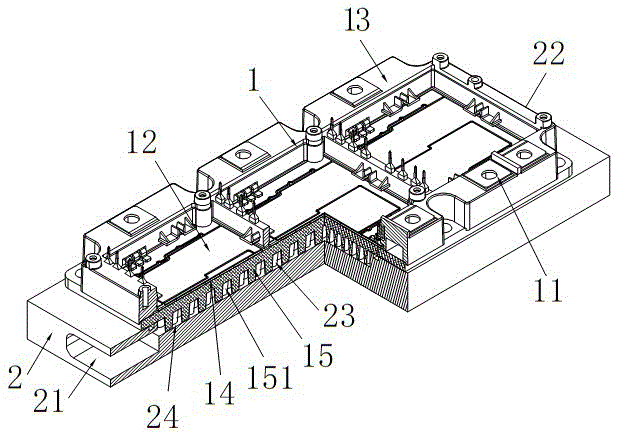
[0029] Such as Figure 8 As shown, the power module 1 is generally composed of a lead terminal 11 , a power chip 12 , a housing 13 , a copper-clad substrate (DBC substrate) 14 and a bottom plate 15 .

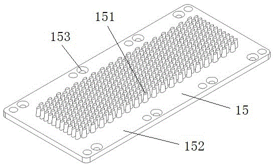
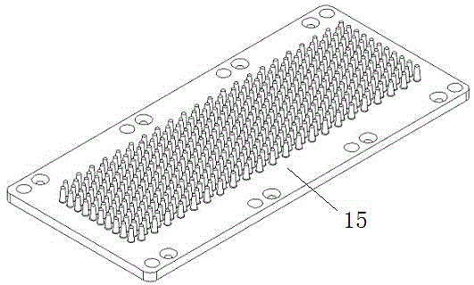
[0030] Such as figure 1 and Figure 4 , 5 , 6 and 7, the integrated liquid cooling device of the power module is connected to the bottom of the power chip 12, the copper clad substrate 14 and the base plate 15 of the power module 1, and includes a square liquid cooling heat sink fixedly connected to the bottom of the base plate 15 2. The heat sink 2 is provided with a liquid channel 24 penetrating from left to right. The top of the liquid channel 24 is provided with a connect...


PUM


Abstract

The invention discloses an integrated liquid cooling heat sink device of a power module and a bottom plate used by the power module. The integrated liquid cooling heat sink device is connected to the bottoms of a power chip, a copper cladding substrate and the bottom plate of the power module and comprises a square liquid cooling heat sink body, wherein the square liquid cooling heat sink body is fixedly connected to the bottom of the bottom plate, a liquid runner is arranged in the heat sink body and penetrates from left to right, a connection cut is arranged at the top position of the liquid runner, a plurality of staggered turbulence columns are arranged at the bottom of the bottom plate, and the staggered turbulence columns of the bottom plate partially pass through the connection cut and are bucked in the liquid runner. With the integrated liquid cooling heat sink device disclosed by the invention, a heat conductive silicon grease layer with poor heat conductivity is removed, the power module and a heat sink are integratedly designed, the heat sink is the bottom plate of the module, a cooling path is shorter, and the cooling efficiency of the power module is further improved; and moreover, the comprehensive structure of the integrated liquid cooling heat sink device is simplified, and the manufacturing cost is reduced.

Description

technical field [0001] The invention relates to the technical field of heat dissipation of power modules used in electric equipment, in particular to an integrated liquid cooling heat dissipation device of a power module and a heat dissipation bottom plate used therefor. Background technique [0002] When designing power conversion equipment, due to the considerable power loss of the conversion equipment itself, it is often necessary to design a bulky heat dissipation system to cool down the equipment. The commonly used heat dissipation methods include natural air cooling, forced air cooling and liquid cooling. , due to the small specific heat capacity of air, air-cooled radiators generally require a large heat dissipation area. Although in recent years, great progress has been made in enhanced heat transfer technology, and the heat transfer efficiency has been continuously improved, making air-cooled radiators smaller and smaller. However, the characteristics of the heat di...

Claims


Application Information

Patent Timeline
IPC IPC(8): H01L23/367H01L23/373H01L23/473
CPCH01L23/367H01L23/373H01L23/3736H01L23/473
Inventor 庄伟东姚二现
Owner 南京银茂微电子制造有限公司
Learn More