Orbital angular momentum vortex wave beam generation apparatus and method

An orbital angular momentum and generating device technology, applied in electrical components, antennas, etc., can solve problems such as low efficiency, beam divergence, complex structure, etc., to reduce complexity, design freedom, and improve radiation efficiency.

Active Publication Date: 2016-05-04
XIDIAN UNIV
View PDF4 Cites 62 Cited by
  • Summary
  • Abstract
  • Description
  • Claims
  • Application Information

AI Technical Summary

Problems solved by technology

[0004] According to the theory of electromagnetic metamaterials and antenna shaped beams, the present invention proposes a device and method for generating orbital angular momentum vortex beams to solve the above-mentioned problems of complex structure, beam divergence and low efficiency in the prior art, and meet the requirements of expanding communication capacity Require

Method used


Image

  • Orbital angular momentum vortex wave beam generation apparatus and method
  • Orbital angular momentum vortex wave beam generation apparatus and method
  • Orbital angular momentum vortex wave beam generation apparatus and method

Examples


Embodiment 1

[0048] Embodiment 1: Generating the orbital angular momentum vortex beam with the card mode l=1.

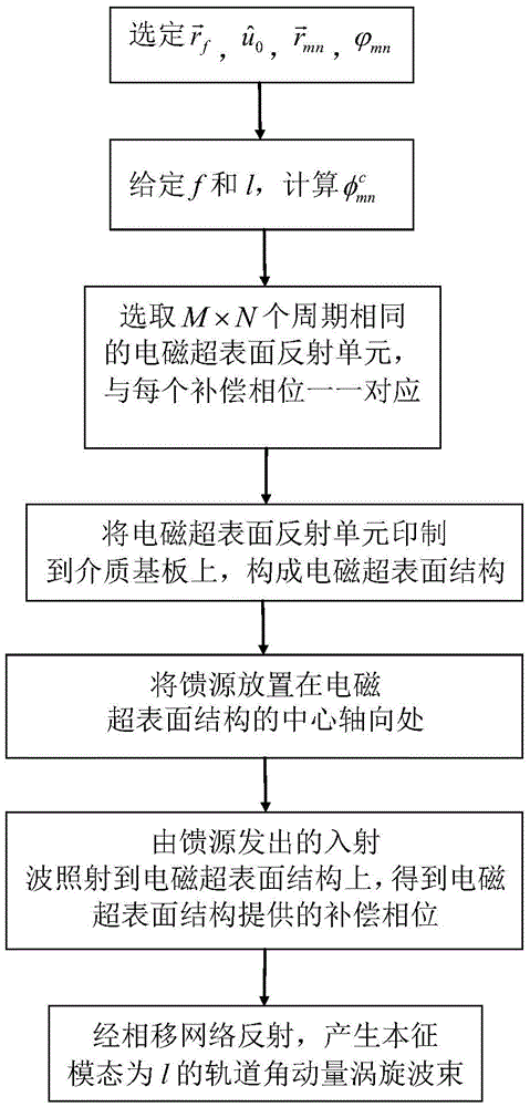
[0049] Step 1, set parameters.

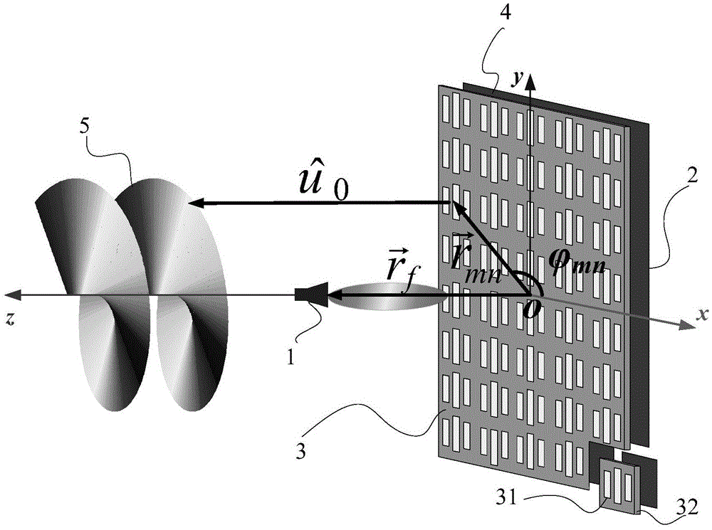
[0050] Take the relative position of the center of the horn antenna m, that is, 0 on the x-axis, 0 on the y-axis, and 0.4 meters on the z-axis; the main beam points to Meters, that is, 0 on the x-axis, 0 on the y-axis, and 1 meter on the z-axis; the total number of rows M=20, the total number of columns N=20, and the distance between the centers of two adjacent electromagnetic metasurface reflection units D=25 mm , the size of the dielectric substrate is 0.5×0.5×0.001 meters, the size of the electromagnetic metasurface reflection unit is 25×25 millimeters, and the distance d=5 millimeters between the metal backplane and the dielectric substrate;

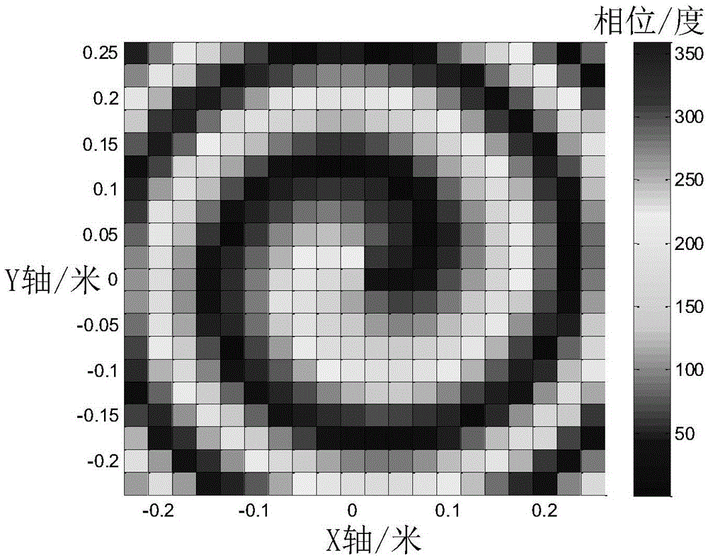
[0051] Step 2, according to the set parameters, calculate the relative position of the magnetic metasurface reflection unit and azimuth angle values

[0052] 2.1) Calculate the relative position...

Embodiment 2

[0067] Embodiment 2: Generate an orbital angular momentum vortex beam with l'=2.

[0068] Step 1, set parameters.

[0069] Take the relative position of the center of the Yagi antenna Meters, that is, 0 on the x-axis, 0 on the y-axis, and 0.3 meters on the z-axis; the main beam points to Meters, that is, 0 on the x-axis, 0 on the y-axis, and 1 meter on the z-axis; the total number of rows M'=22, the total number of columns N'=22, the distance between the centers of two adjacent electromagnetic metasurface reflection units D' = 25mm, the size of the dielectric substrate is 0.55×0.55×0.001m, the size of the electromagnetic metasurface reflection unit is 25×25mm, and the distance d′ between the metal backplane and the dielectric substrate is 10mm.

[0070] Step 2, according to the set parameters, calculate the relative position of the magnetic metasurface reflection unit and azimuth and azimuth angle values

[0071] 2.1) Calculate the relative position of the center of t...


PUM


Abstract

The invention discloses an orbital angular momentum vortex wave beam generation apparatus and method. According to the technical scheme, an electromagnetic super-surface structure (3) is formed by M lines and N columns of electromagnetic super-surface reflection units (31) and dielectric substrates (32); a phase-shifting network (4) is formed by the electromagnetic super-surface structure (3) and a metal back plate (2); the metal back plate (2) is positioned on the back surface of the electromagnetic super-surface structure (3), and the metal back plate is also used as an earth plate; a feed source (1) is put in the central axial position of the electromagnetic super-surface structure (3); incident wave from the feed source (1) irradiates on the electromagnetic super-surface structure; and after the incident wave obtains compensated phase position from the electromagnetic super-surface structure, the incident wave is reflected by the phase-shifting network (4) to generate the orbital angular momentum vortex wave beam(5) with an intrinsic mode 1. According to the orbital angular momentum vortex wave beam generation apparatus and method, the problems of complex technical structure, high cost, beam divergence and low efficiency in the prior art are solved; and the apparatus and method can be used for information transmitting and receiving in the communication technology, and the communication capacity can be increased.

Description

technical field [0001] The invention belongs to the technical field of wireless communication, and in particular relates to a method for generating an orbital angular momentum electromagnetic vortex field, which can be used in radio frequency and microwave bands as a transmitting and receiving device for different modes of orbital angular momentum electromagnetic vortex beam transmission. Background technique [0002] Orbital angular momentum vortex waves have been widely studied and applied in recent years, but the research and application in the fields of radio frequency and wireless communication are relatively lagging behind. Until 2007, B.Thide in Sweden successfully applied it to the field of radio frequency wireless communication by using the method of generating orbital angular momentum OAM by using an array antenna, so the application of OAM electromagnetic vortex field in wireless communication has gradually become a research hotspot today. . So far, the main meth...

Claims


Application Information

Patent Timeline
Patent Type & Authority Applications(China)
IPC IPC(8): H01Q3/26
CPCH01Q3/2605
Inventor 李龙周潇潇余世星石光明朱诚史琰
Owner XIDIAN UNIV
Why Eureka
Try Eureka