Nyquist waveform optical generating device with adjustable duty ratio

A generating device and adjustable technology, which is applied in electromagnetic transmitters, electromagnetic wave transmission systems, electrical components, etc., can solve the problem that the duty cycle cannot be adjusted, and achieve the effect of improving operability and scope of application

Inactive Publication Date: 2016-05-04
BEIJING JIAOTONG UNIV
View PDF10 Cites 2 Cited by
  • Summary
  • Abstract
  • Description
  • Claims
  • Application Information

AI Technical Summary

Problems solved by technology

[0006] The technical problem to be solved by the present invention is: the traditional Nyquist waveform generator based on the optical external modulator, the problem that the duty cycle cannot be adjusted without changing the parameters of the optical external modulator

Method used


Image

  • Nyquist waveform optical generating device with adjustable duty ratio

Examples


Embodiment approach 1

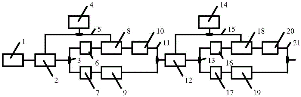
[0019] A Nyquist waveform optical generation device with adjustable duty ratio, such as figure 1 The device shown includes: CW laser 1, Mach-Zehnder modulator-2, 1×2 beam splitter-3, local oscillator source-4, 1×2 bridge-5, polarization controller-6, polarization controller-2 7. Dual parallel Mach-Zehnder modulator 18, optical phase shifter 19, optical amplifier 10, 2×1 optical beam combiner 11, Mach-Zehnder modulator 2 12, 1×2 optical splitter 2 13, this Vibration source 2 14, 1×2 bridge 2 15, polarization controller 3 16, polarization controller 4 17, dual parallel Mach-Zehnder modulator 2 18, optical phase shifter 2 19, optical amplifier 20, 2×1 light combiner two 21;

[0020] The specific connection method is:

[0021] The optical output end of the CW laser 1 is connected to the optical input end of the Mach-Zehnder modulator-2, the optical output end of the Mach-Zehnder modulator-2 is connected to the optical input end of the 1×2 optical splitter-3, and the optical inpu...

Embodiment approach 2

[0026]The optical output end of the CW laser 1 is connected to the optical input end of the Mach-Zehnder modulator-2, the optical output end of the Mach-Zehnder modulator-2 is connected to the optical input end of the 1×2 optical splitter-3, and the optical input end of the local oscillator source-4 The electrical output terminal is connected to the electrical input terminal of the 1×2 bridge-5, and the two electrical output terminals of the 1×2 bridge-5 are respectively connected to the electrical input terminal of the Mach-Zehnder modulator-2 and the dual-parallel Mach-Zehnder modulator The electrical input end of one 8, the two optical output ends of 1×2 optical splitter one 3 are respectively connected to the optical input ends of polarization controller one 6 and polarization controller two 7, and the optical output end of polarization controller one 6 is connected to the double parallel The optical input end of the Mach-Zehnder modulator-8, the optical output end of the d...

Embodiment approach 3

[0031] The optical output end of the CW laser 1 is connected to the optical input end of the Mach-Zehnder modulator-2, the optical output end of the Mach-Zehnder modulator-2 is connected to the optical input end of the 1×2 optical splitter-3, and the optical input end of the local oscillator source-4 The electrical output terminal is connected to the electrical input terminal of the 1×2 bridge-5, and the two electrical output terminals of the 1×2 bridge-5 are respectively connected to the electrical input terminal of the Mach-Zehnder modulator-2 and the dual-parallel Mach-Zehnder modulator The electrical input end of one 8, the two optical output ends of 1×2 optical splitter one 3 are respectively connected to the optical input ends of polarization controller one 6 and polarization controller two 7, and the optical output end of polarization controller one 6 is connected to the double parallel The optical input end of the Mach-Zehnder modulator-8, the optical output end of the ...


PUM


Abstract

The invention discloses a Nyquist waveform optical generating device with an adjustable duty ratio, so as to solve the problem that according to the traditional optical external modulator-based Nyquist waveform generating device, the duty ratio is not adjustable in a condition of not changing parameters of the optical external modulator. The device of the invention can realize that the duty ratio of the generated Nyquist waveform is adjustable in the condition of not changing the system structure and the parameters of the external modulator, the operability and the application range of the optical Nyquist waveform generating device are enhanced greatly, which is extremely useful for the next-generation Nyquist waveform-based all-optical multiplexing communication system. The device is particularly applied to the technical field of communication, radar, sensing and the like.

Description

technical field [0001] The invention relates to a Nyquist waveform optical generating device with adjustable duty cycle, which is suitable for the technical fields of all-optical multiplexing communication system, radar and sensing based on Nyquist waveform. Background technique [0002] With the rapid development of high-speed and large-capacity communication systems, all-optical multiplexing communication systems based on Nyquist waveforms have gradually attracted more and more attention. For example, the optical time division multiplexing system based on the Nyquist waveform can double the capacity of the communication system, which is extremely beneficial to the future all-optical communication network. [0003] The use of optical methods to generate Nyquist waveforms has unique advantages over electronics-based methods, including simple devices, high cost performance, and system miniaturization. The electronic bottleneck problem caused by electronic devices is very ben...

Claims


Application Information

Patent Timeline
Patent Type & Authority Applications(China)
IPC IPC(8): H04B10/50H04B10/532H04B10/54
CPCH04B10/504H04B10/532H04B10/54
Inventor 陈宏尧宁提纲李晶袁瑾张婵
Owner BEIJING JIAOTONG UNIV
Why Eureka
Try Eureka