

Drawing fluid storage mechanism of wire drawing machine
A wire drawing liquid and wire drawing machine technology, applied in the field of cable equipment, can solve the problems of difficult connection, difficult cleaning of equipment, and high sealing requirements, and achieve the effects of high production efficiency, convenient operation and simple processing.
- Summary
- Abstract
- Description
- Claims
- Application Information
AI Technical Summary
Problems solved by technology
Method used
Image

Examples
Embodiment Construction
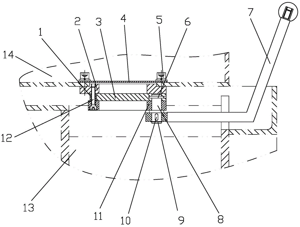
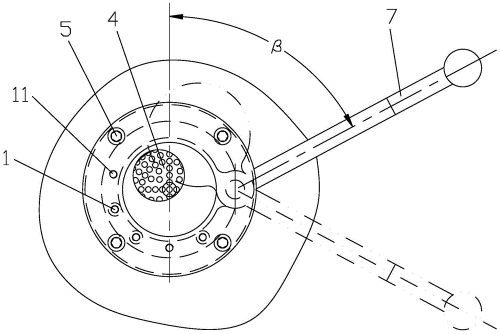
[0023] Such as figure 1 and figure 2 As shown, the present invention includes a base 11, a flange 2, a handle bar 7, a small shaft 8 and a valve plate 3, and the base 11 and the flange 2 are all located between the water tank 14 and the return tank 13, and the flange 2 It is arranged at the bottom liquid outlet of the water tank 14, the base 11 is arranged at the top liquid inlet of the return tank 13, the flange 2 is fixedly connected with the water tank 14, and the flange 2 is fixedly connected with the base 11, A plurality of spacers 1 are arranged between the flange 2 and the base 11, the flange 2, the base 11 and the spacers 1 jointly form a valve plate cavity, and the valve plate 3 is arranged in the valve plate cavity One end of the handle rod 7 penetrates into the liquid return tank 13 and the end is fixedly connected with the lower end of the small shaft 8, the small shaft 8 is vertically arranged, and the upper end of the small shaft 8 passes through the base 11 an...
PUM
 Abstract
Description
Claims
Application Information