Nonmetal position sensor, antenna automatic positioning device and antenna automatic positioning system for electromagnetic compatibility test
An electromagnetic compatibility and automatic positioning technology, which is applied in the direction of antenna support/installation device, measuring device, and fluid device, can solve problems such as improper positioning, low efficiency, and affecting test accuracy, and achieve simple assembly and measurement accuracy High, realize the effect of automatic detection and automatic control
- Summary
- Abstract
- Description
- Claims
- Application Information
AI Technical Summary
Problems solved by technology
Method used
Image

Examples
Embodiment 1
[0037] Embodiment 1 A non-metallic position sensor for electromagnetic compatibility testing
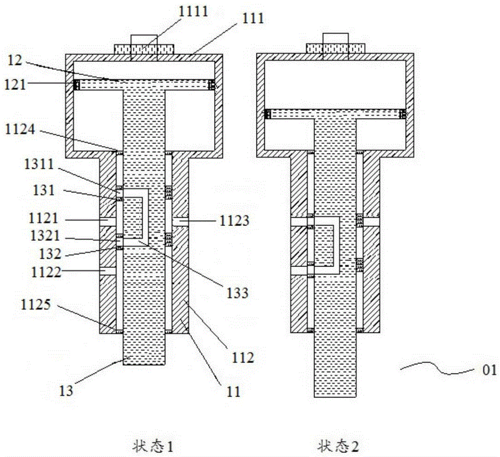
[0038] figure 1 It is a cross-sectional view of the non-metallic position sensor 01 used for electromagnetic compatibility testing provided by the embodiment of the present invention.
[0039] Such as figure 1As shown, the non-metallic position sensor 01 includes a cylinder 11, a piston 12 accommodated in the cylinder 11, and a piston rod 13 fixedly connected to the piston 12 at one end; the cylinder 11 includes an upper chamber 111 of the cylinder and the cylinder lower chamber 112; the side wall of the cylinder lower chamber 112 is provided with a first radial air hole 1121, a second radial air hole 1122 arranged at the lower end of the first radial air hole 1121, and the first diameter A third radial air hole 1123 axially symmetrical to the air hole 1121;
[0040] The position where the piston rod 13 is combined with the inner wall of the cylinder lower chamber 112 is provided ...
Embodiment 2
[0057] Embodiment 2 An automatic antenna positioning device
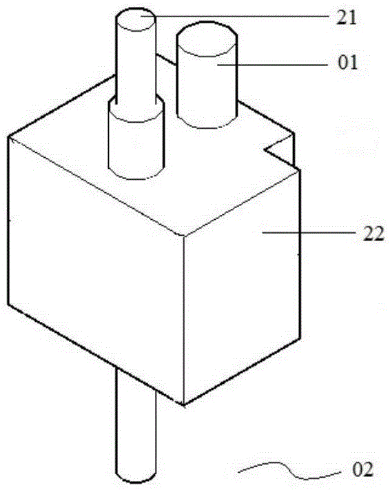
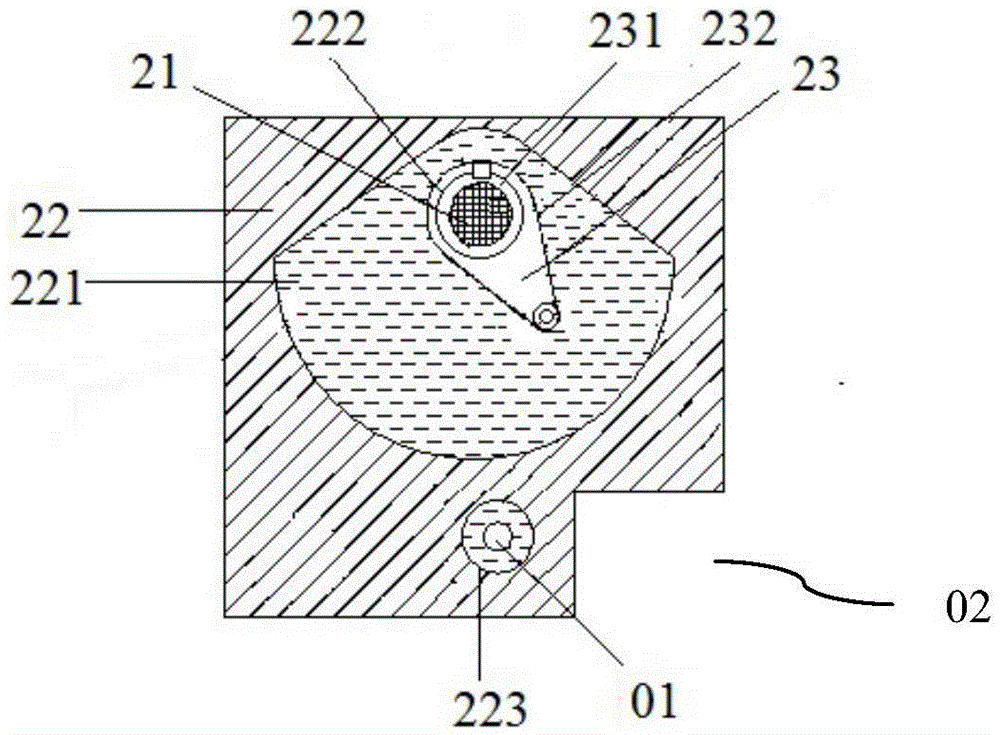
[0058] figure 2 It is a schematic structural diagram of the antenna automatic positioning device 02 provided by the embodiment of the present invention; image 3 It is a cross-sectional view of the antenna automatic positioning device 02 provided by the embodiment of the present invention; Figure 4 It is a schematic diagram of the connection between the antenna 21 and the rotating sleeve 22 provided by the embodiment of the present invention.
[0059] Such as Figure 2-4 As shown, in one embodiment of the present invention, the antenna automatic positioning device 02 provided by the present invention includes the non-metallic position sensor 01 provided in Embodiment 1 of the present invention, and also includes a connecting piece 22 and a rotating sleeve arranged on the connecting piece 22 23. The antenna 21 set in the rotating sleeve 23 and the non-metallic position sensor 01 are set on the connecting piece 2...
Embodiment 3
[0072] Embodiment 3 An antenna automatic positioning system
[0073] Image 6 It is a schematic diagram of an antenna automatic positioning system 03 provided by an embodiment of the present invention.
[0074] Such as Image 6 As shown, the present invention provides an automatic antenna positioning system 03, including the automatic antenna positioning device 02 provided by the present invention, and also includes a gas-electric conversion device connected to the non-metallic position sensor 01 in the automatic antenna positioning device 02, and a gas-electric The position control device connected to the conversion device; wherein, when the piston rod 13 of the non-metallic position sensor 01 in the antenna automatic positioning device 02 rises to the first radial air hole 1121 and the third radial air hole 1123 conduction, the non-metallic position sensor 01 Sending the first air pressure signal to the gas-to-electric conversion device; then the gas-to-electricity convers...
PUM
 Abstract
Description
Claims
Application Information
 - Generate Ideas
- Intellectual Property
- Life Sciences
- Materials
- Tech Scout
- Unparalleled Data Quality
- Higher Quality Content
- 60% Fewer Hallucinations
Browse by: Latest US Patents, China's latest patents, Technical Efficacy Thesaurus, Application Domain, Technology Topic, Popular Technical Reports.
© 2025 PatSnap. All rights reserved.Legal|Privacy policy|Modern Slavery Act Transparency Statement|Sitemap|About US| Contact US: help@patsnap.com