
Near-field antenna for RFID system

A near-field antenna and radome technology, applied in the field of communications, can solve the problems of poor near-field antenna gain and field strength, blind spots, etc., and achieve the effects of easy processing, high production efficiency, and stable performance

Inactive Publication Date: 2016-05-11
ZTE INTELLIGENT IOT TECH
View PDF5 Cites 9 Cited by
  • Summary
  • Abstract
  • Description
  • Claims
  • Application Information

AI Technical Summary

Problems solved by technology

However, the gain and field strength of the existing near-field antennas are not very good, and there will be blind spots in the near-field range of the antenna, so how to design an antenna with high gain, excellent performance, strong near-field strength, and no blind spots in the near-field range of the antenna The near-field antenna becomes the subject of research by those skilled in the art

Method used


Image

  • Near-field antenna for RFID system
  • Near-field antenna for RFID system
  • Near-field antenna for RFID system

Examples


Embodiment Construction

[0025] It should be noted that, in the case of no conflict, the embodiments of the present invention and the features in the embodiments can be combined with each other.

[0026] The present invention will be described in detail below with reference to the accompanying drawings and examples.

[0027] First, the principle of the near-field antenna is introduced:

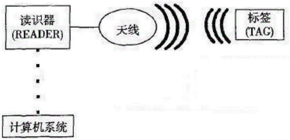
[0028] The near-field antenna mainly uses the near-field characteristics of the antenna. The near-field area of ​​the antenna, also known as the induction area, can simply be considered as the near-field energy of the antenna is stored in the structural inductance and structural capacitance of the antenna. When two antennas are in the near-field region of each other and communicate mainly through magnetic energy (mutual inductance) coupling, the two antennas are called near-field magnetic antennas. Loop antennas are the most common and work like a transformer.

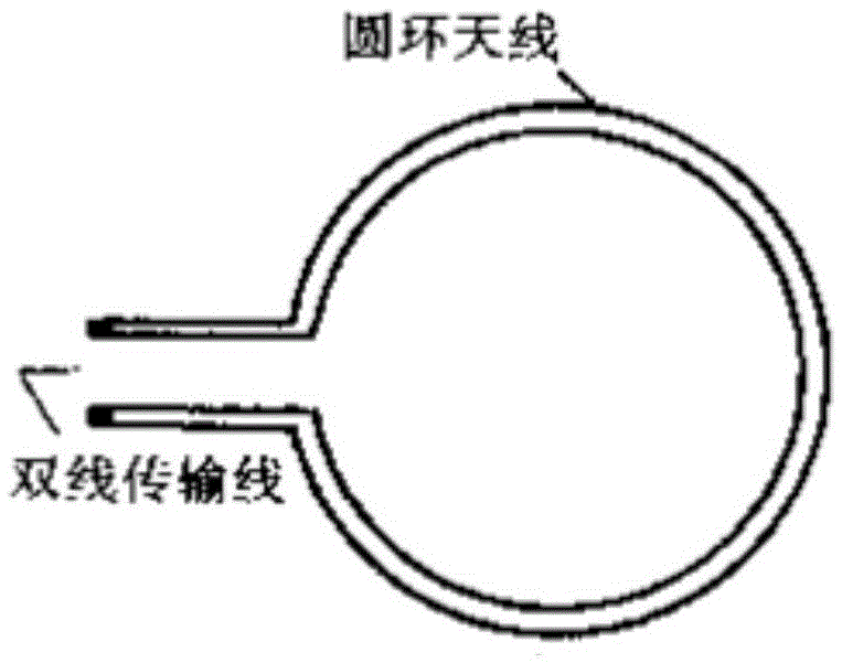
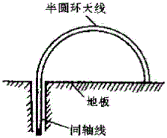
[0029] The near-field antenna is in the form of a loo...


PUM


Abstract

The invention provides a near-field antenna for an RFID system. The near-field antenna comprises a substrate, a bottom shell and a connection feeder, wherein three concentric copper rings with different widths and radiuses are paved on a copper-paved radiation surface of the substrate; the copper ring with the maximal diameter is connected with a core wire of an N-type connector through the connection feeder; the substrate is fixed on the bottom shell through a positioning column at the bottom part; and an antenna cover is arranged on the bottom shell. The near-field antenna for the RFID system has the advantages that the form of a microstrip line with the concentric rings is adopted by the antenna, so that the near-field antenna is easy to process and high in efficiency; an aluminum shell at the lower part of a radiation panel can strengthen the antenna radiation intensity; and an upper shell right above the radiation panel is made of a PC (polycarbonate) material which does not affect radiation right above the antenna, so that the near-field antenna has high radiation intensity, high gain and stable performance.

Description

technical field [0001] The invention belongs to the communication field, and in particular relates to a near-field antenna for an RFID system. Background technique [0002] The current radio frequency identification (RFID) industry is developing very fast, and it has begun to be widely used in many fields such as transportation, logistics, and monitoring. The RFID system consists of readers, antennas and tags (refer to the RFID system diagram: figure 1 ). The reader transmits signals to the tag through the antenna, and the tag reflects the signal to the reader antenna to form a complete communication link. In the communication process, since the polarization of the tag is linearly polarized, the antenna of the reader is also made of linearly polarized, so that the tag can be well matched with the antenna of the reader and accurately identified. In the RFID system, the reader antenna is divided into two types, one is the far-field antenna; this type of antenna is used for ...

Claims


Application Information

Patent Timeline
Patent Type & Authority Applications(China)
IPC IPC(8): H01Q1/36H01Q1/38H01Q1/42H01Q1/50
CPCH01Q1/36H01Q1/38H01Q1/42H01Q1/50
Inventor 甄珍贾旭峰
Owner ZTE INTELLIGENT IOT TECH
Learn More