Planar antenna having reconfigurable radiation pattern

A flat-panel antenna and substrate technology, applied to the structural form of the radiation element, antenna, antenna grounding device, etc., can solve the problems of RF energy transmission not as good as the horizontal direction, differential voltage standing wave ratio, high manufacturing accuracy, etc., and achieve low cost and high impedance Good matching performance and high manufacturing precision

Active Publication Date: 2016-05-11
ALCATEL LUCENT SHANGHAI BELL CO LTD
View PDF4 Cites 9 Cited by
  • Summary
  • Abstract
  • Description
  • Claims
  • Application Information

AI Technical Summary

Problems solved by technology

This design still has some disadvantages: (1) the size is large, the height of the antenna depends on the height of the driving element, which is usually a single stage, and in order to improve the reflection effect of the ground, it needs a certain length of the sleeve; (2) the impedance changes , when the parasitic element is switched between reflector and director mode of operation, the input impedance at the active / driven element (feed point) will change significantly due to the effect of mutual coupling, resulting in poor VSWR (Voltage Standing wave ratio); (3) higher manufacturing precision is required; (4) RF energy transmission of vertical polarization is not as good as that of horizontal direction

Method used


Image

  • Planar antenna having reconfigurable radiation pattern
  • Planar antenna having reconfigurable radiation pattern
  • Planar antenna having reconfigurable radiation pattern

Examples


Embodiment Construction

[0029] Hereinafter, preferred embodiments of the present disclosure will be described in more detail with reference to the accompanying drawings. Although the drawings show preferred embodiments of the present disclosure, it should be understood that the present disclosure can be implemented in various forms and should not be limited by the embodiments set forth herein. On the contrary, these embodiments are provided to make the present disclosure more thorough and complete, and to fully convey the scope of the present disclosure to those skilled in the art.

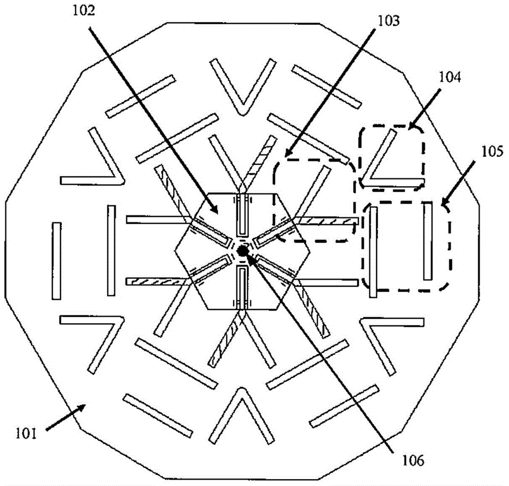
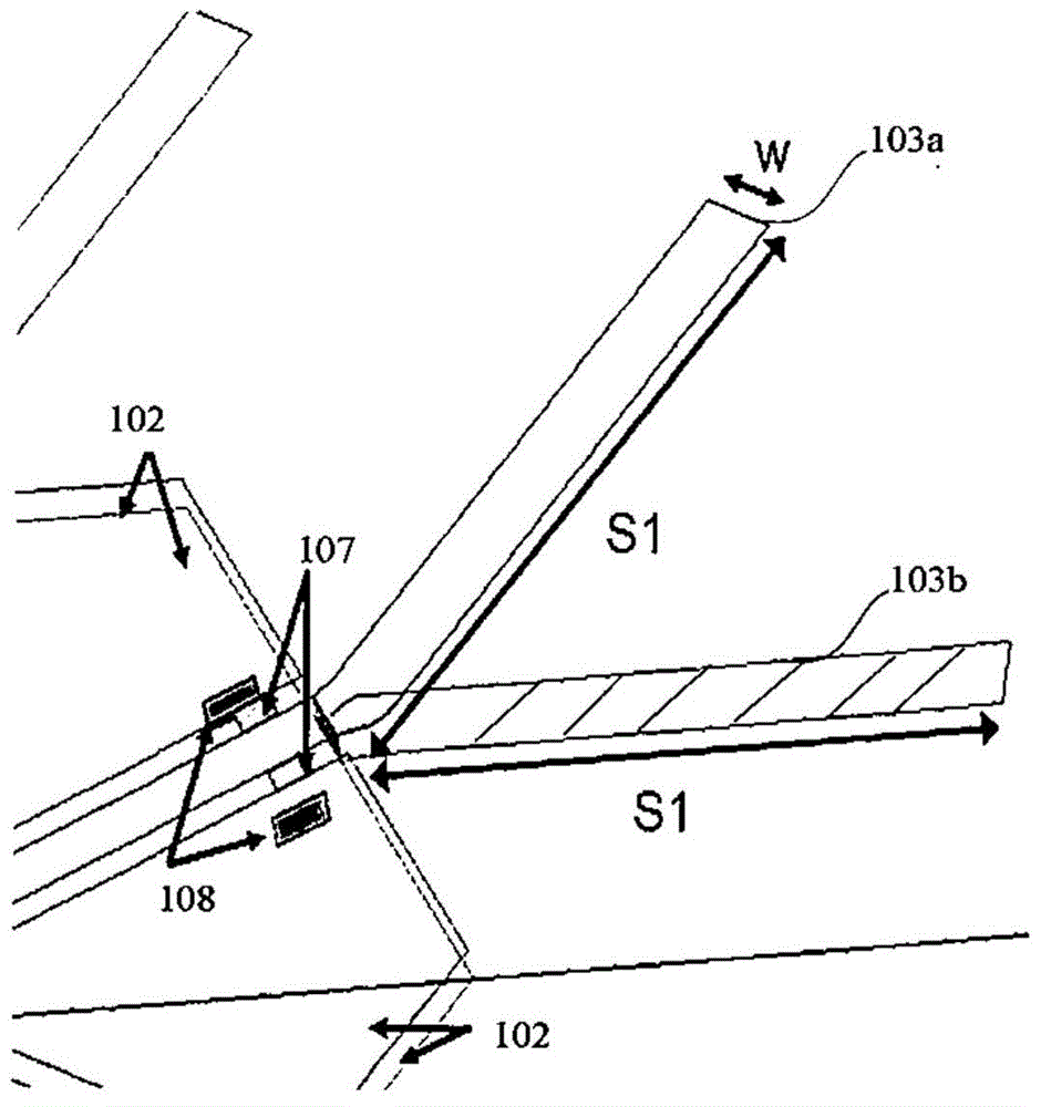
[0030] In the present invention, a panel antenna with reconfigurable antenna beam is proposed. In particular, the flat panel antenna includes a V-shaped flat panel dipole driving element, a V-shaped director, and some linear reflectors.

[0031] figure 1 It is a schematic diagram of a panel antenna according to an embodiment of the present invention.

[0032] The flat panel antenna 10 includes: a substrate 101 with two parall...


PUM


Abstract

The invention provides a planar antenna having a reconfigurable radiation pattern. The planar antenna comprises a substrate, a grounding plate, a plurality of driving units, and a plurality of parasitic element groups. The grounding plate is disposed on the central area of the substrate, and can work in a main reflector mode. The plurality of driving units are arranged symmetrically on the periphery of the grounding plate in a radial direction. Each of the plurality of parasitic element groups comprises a director and an emitter, and the directors and the emitters are disposed on the outer side of the substrate according to the positions of the driving units. The antenna provided by the invention has advantages of small size, high production precision, low costs, simple feed network, good impedance matching performance, and high RF energy transmission capability.

Description

Technical field [0001] The present invention generally relates to the field of wireless communication, and more specifically, to a panel antenna with a reconfigurable radiation pattern. Background technique [0002] In small cells, the antenna radiation pattern needs to be changed to meet the needs of coverage sector, capacity performance, or interference suppression. The antenna array method can be used, but this will cause the antenna shape to become larger and the cost will increase significantly. The reconfigurable radiation pattern antenna provides a low-cost and feasible alternative for the base station of the small cell. [0003] Among many reconfigurable pattern antennas, ESPAR (Electronic Controllable Passive Array Radiator) antenna is an optional solution for many wireless communication applications. For a typical ESPAR antenna, a single active element is surrounded by multiple identical parasitic elements. Use varactor diodes to load the bottom of each parasitic eleme...

Claims


Application Information

Patent Timeline
Patent Type & Authority Applications(China)
IPC IPC(8): H01Q1/38H01Q1/48H01Q19/10
Inventor 陆金星王伟徐朝军沈钢
Owner ALCATEL LUCENT SHANGHAI BELL CO LTD
Why Eureka
Try Eureka