Optical network equipment, optical module and optical link detection method

A technology of optical network equipment and optical modules, which is applied in the field of optical communication, can solve problems such as high cost, difficulty in ensuring 100% installation, and difficulty in popularization, and achieve the effect of low cost, saving original parts, and unified assembly

Active Publication Date: 2016-05-11
CHINA TELECOM CORP LTD
View PDF4 Cites 3 Cited by
  • Summary
  • Abstract
  • Description
  • Claims
  • Application Information

AI Technical Summary

Problems solved by technology

[0004] However, fiber Bragg gratings generally cost tens of yuan, and the cost is high, so it is difficult to popularize in the short term; when installing reflectors in flanges or cold joints, it is necessary to change the structure of the flange / cold joint or the splicing scene of the leather wire fiber. It is generally difficult to guarantee 100% installation; some devices need to be installed by on-site installation and maintenance personnel, and the requirements for the control of on-site construction operations are high

Method used


Image

  • Optical network equipment, optical module and optical link detection method
  • Optical network equipment, optical module and optical link detection method
  • Optical network equipment, optical module and optical link detection method

Examples


Embodiment Construction

[0030] The present invention will be described more fully below with reference to the accompanying drawings, in which exemplary embodiments of the present invention are illustrated.

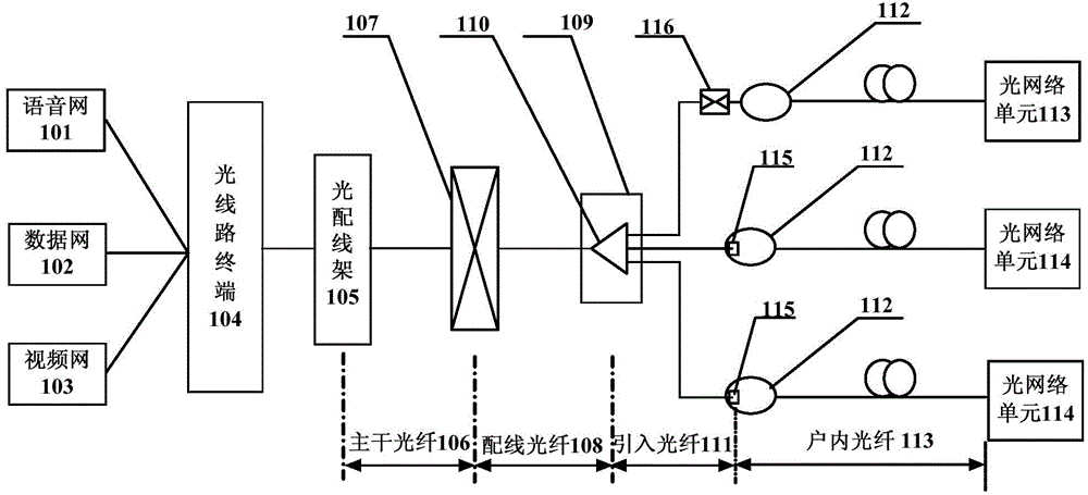
[0031] figure 1 Shows a schematic structural diagram of an optical communication system according to an embodiment of the present invention. Such as figure 1 As shown, the optical communication system mainly includes: voice network 101, data network 102, video network 103, OLT104 (opticalline terminal, optical line terminal), optical distribution frame ODF105, backbone fiber 106, optical junction box 107, distribution fiber 108 , Optical fiber distribution box 109, optical splitter 110, incoming optical fiber 111, optical fiber socket box 112, indoor optical fiber 113, optical network unit 114, on-site optical network equipment such as terminal 115, cold connector 116.

[0032] In a PON (Passive Optical Network, passive optical network) system, the PON uses a single optical fiber to connect to the OLT...


PUM


Abstract

The invention discloses optical network equipment, an optical module and an optical link detection method. The optical module comprises a coupling lens located in the optical module and a dielectric film reflector, wherein a surface of the coupling lens, which is close to a side of a detector or a laser, is plated with a dielectric film so as to form the dielectric film reflector; and the dielectric film reflector is used for reflecting a test signal of a detector and transmitting a work signal. By using the optical network equipment, the optical module and the optical link detection method provided in the invention, the dielectric film reflector formed through plating the dielectric film on the coupling lens of the optical module can realize an optical link measurement and diagnosis function based on OTDR; cost is low, components are saved and unification assembling can be achieved; OTDR detection can be realized without changing a device structure in an optical communication system.

Description

Technical field [0001] The present invention relates to the field of optical communication, in particular to an optical network device, an optical module and an optical link detection method. Background technique [0002] OTDR (Optical Time Domain Reflectometer, Optical Time Domain Reflectometer) is a sophisticated optoelectronic integrated instrument that uses the Rayleigh scattering and Fresnel reflection generated by the light transmission in the optical fiber to measure and diagnose the optical link. It is widely used in the maintenance and construction of optical cable lines. It can measure the length of optical fiber, transmission attenuation, joint attenuation and fault location. When using an OTDR to perform optical link measurement and diagnosis in an optical communication system, it is faced with the problem of how to achieve optical path performance measurement and fault location. Especially in the PON (Passive Optical Network, Passive Optical Network) optical access ...

Claims


Application Information

Patent Timeline
Patent Type & Authority Applications(China)
IPC IPC(8): H04B10/071
Inventor 沈成彬杜喆王波蒋铭
Owner CHINA TELECOM CORP LTD
Why Eureka
Try Eureka