
Joint reconstruction of electron density images.

A technology of electron density and image, applied in the field of image generation, can solve problems such as inability to make

Inactive Publication Date: 2016-05-11
KONINKLJIJKE PHILIPS NV
View PDF5 Cites 4 Cited by
  • Summary
  • Abstract
  • Description
  • Claims
  • Application Information

AI Technical Summary

Problems solved by technology

It appears that image contrast (i.e., relative differences between image elements) can be more pronounced in either attenuation-based imaging or refractive index-based imaging, and it does not seem possible to make is a better overview

Method used


Image

  • Joint reconstruction of electron density images.
  • Joint reconstruction of electron density images.
  • Joint reconstruction of electron density images.

Examples


Embodiment Construction

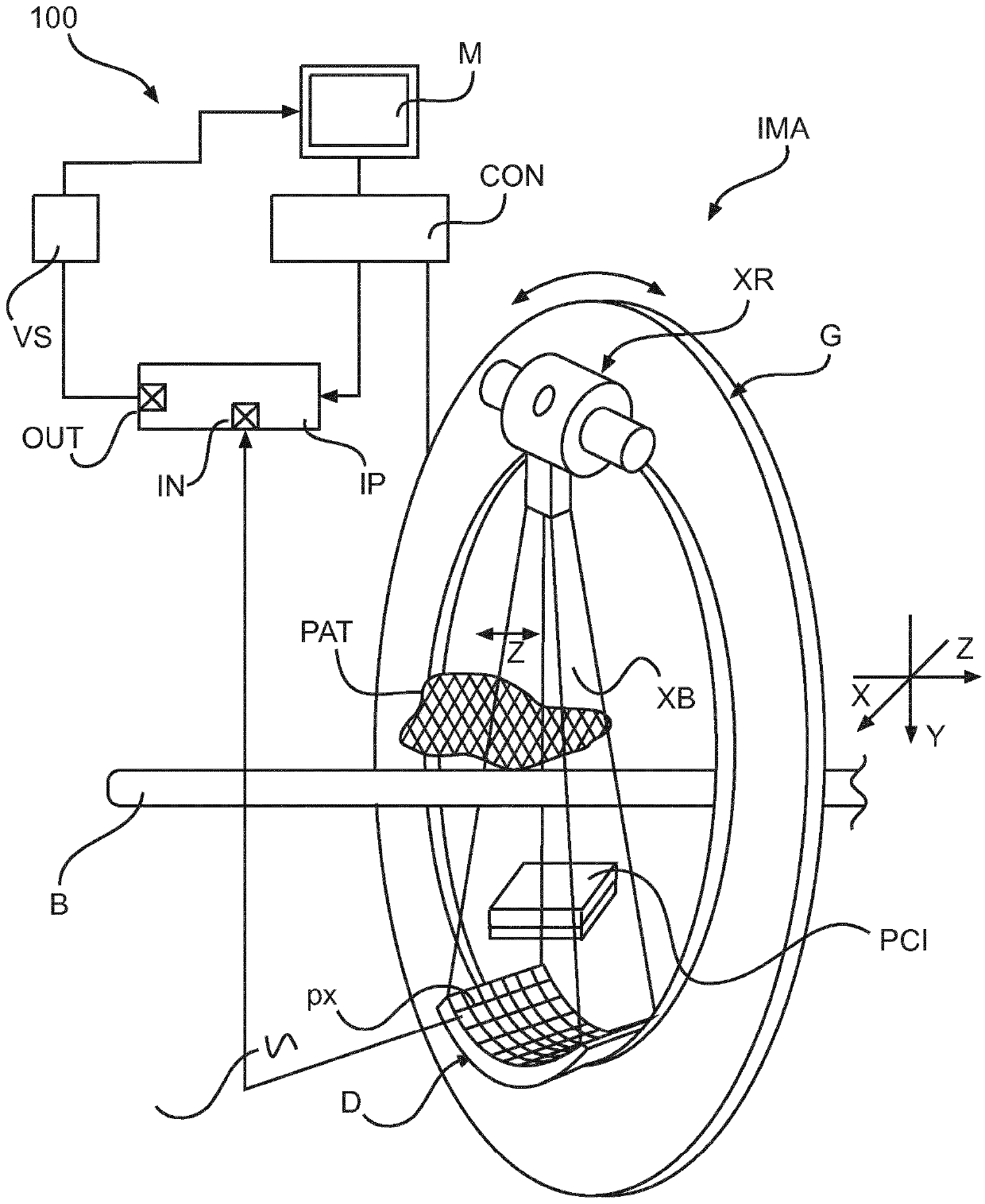
[0025] refer to figure 1 , shows an imaging system according to one embodiment. Broadly, the imaging arrangement comprises an X-ray based CT scanner IMA and a workstation or operator console CON for controlling the operation of the scanner IMA.

[0026] A general purpose computing system can act as an operator console CON and include output devices (eg, display M) and input devices (eg, keyboard, mouse, etc.). Software residing on the console CON allows the operator to control the operation of the system IMA, for example allowing the operator to select imaging parameters directly or indirectly by selecting a pre-generated imaging protocol. A display unit (e.g. monitor / screen) M is communicatively coupled to the console CON to aid in the input of control information or to observe the operating state of the scanner or to observe the image supplied by the scanner or to obtain the operating state of the image by image processing the image so supplied . There is also an image pr...


PUM


Abstract

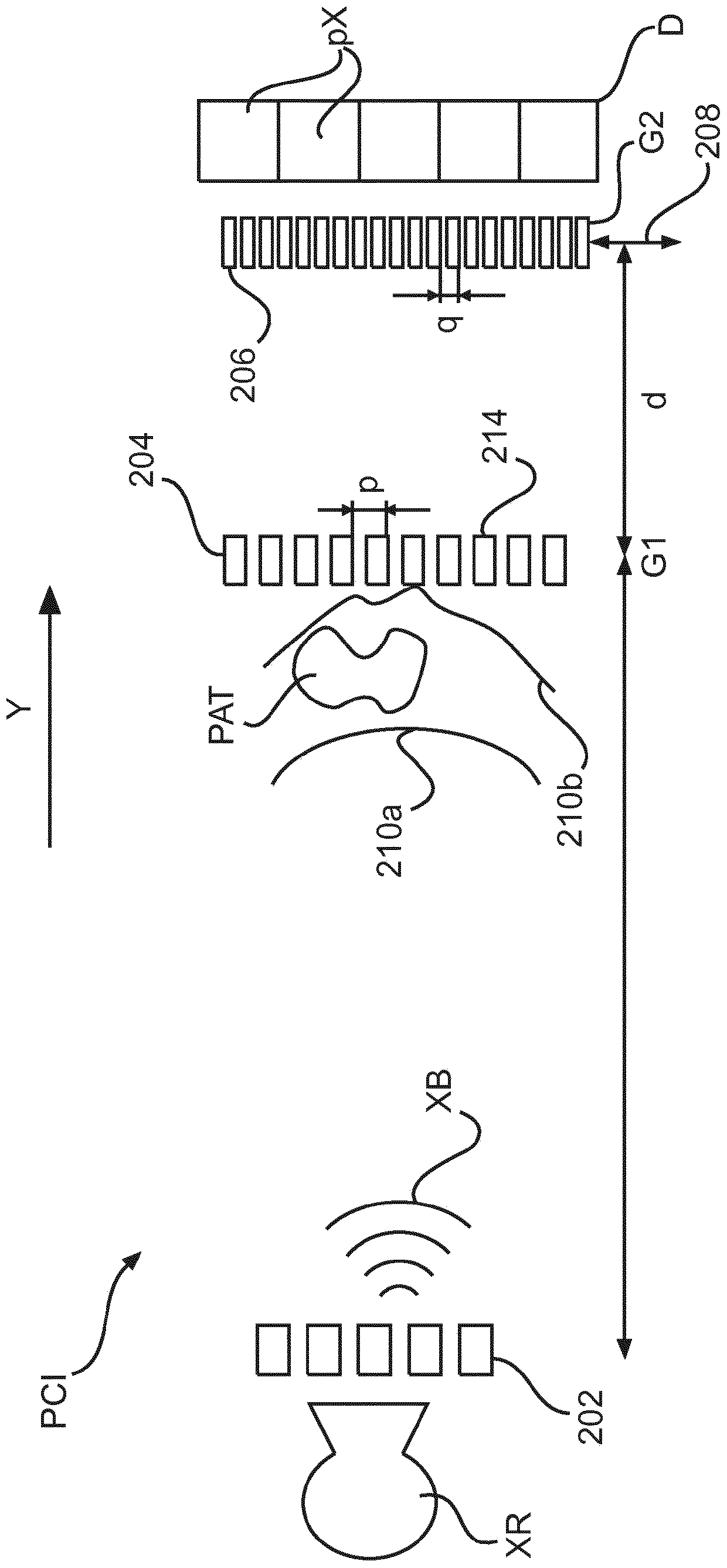
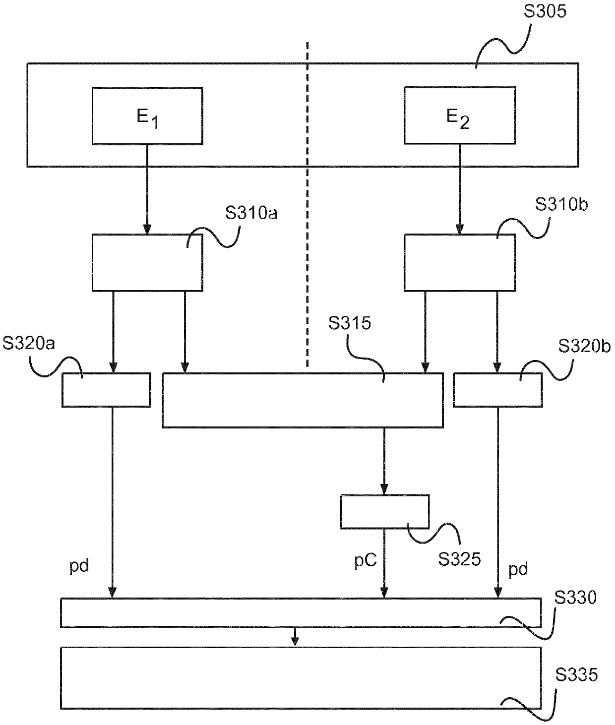
A method and a related system (IMA) for reconstructing an image of an electron density in a subject PAT. An x-ray radiation imager is used to expose the subject PAT to radiation to receive projection data. The reconstruction method combines projection data from two channels, namely Compton scatter based attenuation data pC and phase shift data pd Phi.

Description

technical field [0001] The invention relates to a method for generating an image, an image processing system, a computer program element and a computer readable medium. Background technique [0002] Conventional X-ray imaging focuses on attenuation as a physical quantity that provides contrast between various types of human tissue. More recently, other imaging techniques like dual energy imaging or phase contrast imaging provide information on different physical quantities like electron density, refractive index gradient or scattering cross section of the imaged tissue. It appears that image contrast (i.e., relative differences between image elements) can be more pronounced in either attenuation-based imaging or refractive index-based imaging, and it does not seem possible to make is a better overview. Contents of the invention [0003] Therefore, there may be a need for a method and related apparatus or system for image generation to robustly improve image quality in a ...

Claims


Application Information

Patent Timeline
IPC IPC(8): G06T11/00
Inventor T·克勒B·J·布伦德尔E·勒斯尔
Owner KONINKLJIJKE PHILIPS NV
Learn More