
Building block bisecting machine

A technology for cutting machines and blocks, which is applied in mechanical equipment, stone processing tools, fluid pressure actuating devices, etc. It can solve the problems of many impurities, high labor intensity, and easy damage of blocks, so as to increase the matching area and facilitate operation , the effect of compact structure

Active Publication Date: 2016-05-18
李宏德
View PDF7 Cites 1 Cited by
  • Summary
  • Abstract
  • Description
  • Claims
  • Application Information

AI Technical Summary

Problems solved by technology

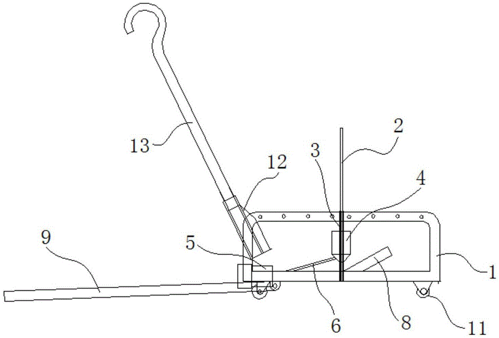
[0005] The purpose of the present invention is to provide a block cutting machine, so as to overcome the existing shortcomings of manual cutting of aerated concrete blocks, such as high labor intensity, easy damage of blocks and more impurities.

Method used


Image

  • Building block bisecting machine
  • Building block bisecting machine
  • Building block bisecting machine

Examples


Embodiment Construction

[0032] The specific embodiments of the present invention will be described in detail below in conjunction with the accompanying drawings, but it should be understood that the protection scope of the present invention is not limited by the specific embodiments.

[0033] Unless expressly stated otherwise, throughout the specification and claims, the term "comprise" or variations thereof such as "includes" or "includes" and the like will be understood to include the stated elements or constituents, and not Other elements or other components are not excluded.

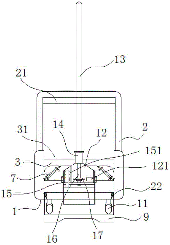
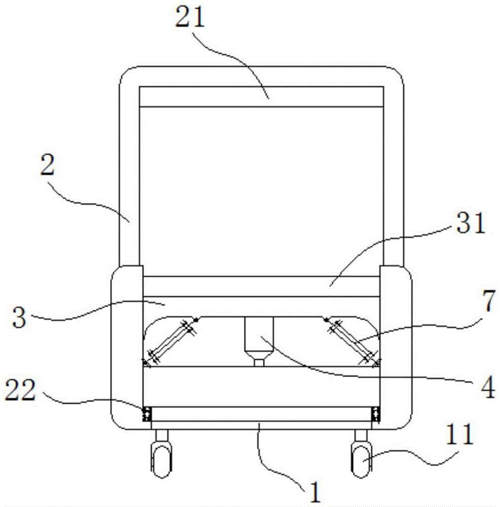
[0034] Figure 1 to Figure 7 It shows a schematic structural view of a block cutting machine according to a preferred embodiment of the present invention. The block cutting machine includes a machine base 1, an upper knife rest 2, an upper knife 21, a lower knife seat 3, a lower knife 31 and a pushing institutions such as Figure 1 to Figure 3 As shown, the two sides of the lower end of the upper knife rest 2 are respecti...


PUM


Abstract

The invention discloses a building block bisecting machine. The building block bisecting machine comprises a machine seat, an upper cutter rest, an upper cutter, a lower cutter seat, a lower cutter and a pushing mechanism, wherein the lower end of the upper cutter frame is supported on the machine seat through a supporting spring; the upper cutter is erected at the upper end of the upper cutter rest; the lower cutter seat is arranged on the upper cutter rest in a vertical sliding mode; the lower cutter is arranged at the upper end of the lower cutter seat and located under the upper cutter; the pushing mechanism is clamped between the lower end of the upper cutter rest and the lower end of the lower cutter seat and used for driving the lower cutter seat to ascend and descend. The upper cutter and the lower cutter right face each other. When the pushing mechanism drives the lower cutter seat to ascend, the upper cutter rest squeezes the supporting spring to descend under the action of counter-acting force, the upper cutter and the lower cutter bisect a building block, and then the building block cracks and is broken. The building block bisecting machine is simple in structure, convenient to operate and free of block-shaped impurities in the cutting process, thereby being environmentally friendly.

Description

technical field [0001] The technology involved in the invention belongs to the mechanical application category, which is a mechanical hydraulic and hydraulic transmission technology, which is applied in the field of construction and aerated concrete block production, and particularly relates to a block cutting machine. Background technique [0002] With the development of society and the wide use of various new materials, block is an important new material. For example, a new type of aerated concrete block is widely used in construction now, because aerated concrete Blocks are made of industrial waste such as coal ash and dust, so it is a new type of building material that is energy-saving, environmentally friendly and reusable. Air-entrained concrete blocks are light in weight, fast to build walls, and the walls are solid and strong, and they are widely used all over the world. [0003] But up to now, the cut-off of the aerated concrete block is mainly cut off manually, an...

Claims


Application Information

Patent Timeline
Patent Type & Authority Applications(China)
IPC IPC(8): B28D1/22F15B13/02
CPCB28D1/222F15B13/02
Inventor 李宏德
Owner 李宏德
Learn More