Pulling shearing conveyer device

A technology for conveying devices and conveyor belts, which is applied to conveyors, transportation and packaging, etc. It can solve the problems of increasing spare parts costs, increasing production costs, and damage to rubber roller conveyor belts, so as to save spare parts costs, reduce damage frequency, and reduce labor. intensity effect

Inactive Publication Date: 2016-05-18
王亚男
View PDF0 Cites 1 Cited by
  • Summary
  • Abstract
  • Description
  • Claims
  • Application Information

AI Technical Summary

Problems solved by technology

[0002] Traditional devices often cause damage to rubber rollers and conveyor belts, resulting in frequent repla

Method used


Image

  • Pulling shearing conveyer device

Examples


Example Embodiment

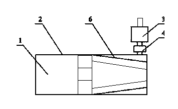
[0009] The present invention will be further explained below in conjunction with the drawings.

[0010] A stretch-cutting conveying device, which is characterized in that it comprises a conveyor belt (1), a baffle (2), a motor (3), a motor pinion box (4), a rubber roller (5) and a copper plate (6); among them, Two baffles (2) are respectively installed on both sides of the conveyor belt (1), and a copper plate (6) is placed on the output end of the conveyor belt (1) on the inner side of the baffle (2), and two copper plates ( The end of 6) is slightly folded inward along the running direction of the conveyor belt (1); the four corners of the copper plate (6) and the baffle (2) are connected by bolts, and the copper plate (5) can be changed by adjusting the position of the nut Collapse the angle.

[0011] The above content is only a preferred embodiment of the present invention, and is not intended to limit the implementation of the present invention. Appropriate variations or modi...


PUM


Abstract

The invention discloses a pulling shearing conveyer device. The pulling shearing conveyer device is characterized in that the device comprises a conveying belt (1), baffles (2), a motor (3), a motor pinion box (4), a rubber roller (5) and copper plates (6); the two baffles (2) are installed on the two sides of the conveying belt (1) correspondingly, each copper plate (6) is arranged on the part, at the output end of the conveying belt (1), of the inner side of the corresponding baffle (2), and the ends of the two copper plates (6) are slightly closed up inward in the operating direction of the conveying belt (1); the four corners of each copper plate (6) are connected with the corresponding baffle (2) through bolts, and the close-up angles of the copper plates (6) can be changed by adjusting the positions of nuts. According to the pulling shearing conveyer device, raw material consumption is reduced, the damage frequency of the machine is decreased, and the labor intensity of maintenance personnel is relieved; the expenses of replacement parts are reduced, considerable economic benefits are created, and the safety of operating personnel during producing is ensured.

Description

technical field [0001] The invention relates to the field of pulling and shearing machines, in particular to a pulling and shearing conveying device. Background technique [0002] Traditional devices often cause damage to rubber rollers and conveyor belts, resulting in frequent replacement of rubber rollers and conveyor belts, increasing the cost of spare parts and increasing production costs. In view of the above problems, a device was invented to further improve the conveyor of the breaking machine. Contents of the invention [0003] In view of the above problems, the technical problem to be solved by the present invention is to provide a pull-shear conveying device. [0004] A pulling and shearing conveying device, characterized in that it includes a conveyor belt (1), a baffle (2), a motor (3), a motor pinion box (4), a rubber roller (5) and a copper plate (6); wherein, Two baffles (2) are respectively installed on both sides of the conveyor belt (1), and a copper pl...

Claims


Application Information

Patent Timeline
IPC IPC(8): B65G21/20B65G15/00
Inventor 王亚男
Owner 王亚男
Why Eureka
Try Eureka