Preparing method for in-situ synthesis oriented growth M7C3 coating

A technology of directional growth and in-situ synthesis, applied in the field of wear-resistant coatings, can solve problems such as inability to prepare, and achieve the effects of low consumption of raw materials, easy control, and simple equipment

Pending Publication Date: 2017-08-08
CHINA THREE GORGES UNIV
View PDF5 Cites 2 Cited by
  • Summary
  • Abstract
  • Description
  • Claims
  • Application Information

AI Technical Summary

Problems solved by technology

[0004] In the above scheme, the prepared wear-resistant material is in the form of a whole block, and the size of the material block is limited by the diameter of the quar

Method used


Image

  • Preparing method for in-situ synthesis oriented growth M7C3 coating
  • Preparing method for in-situ synthesis oriented growth M7C3 coating
  • Preparing method for in-situ synthesis oriented growth M7C3 coating

Examples


Example Embodiment

[0043] Example 1

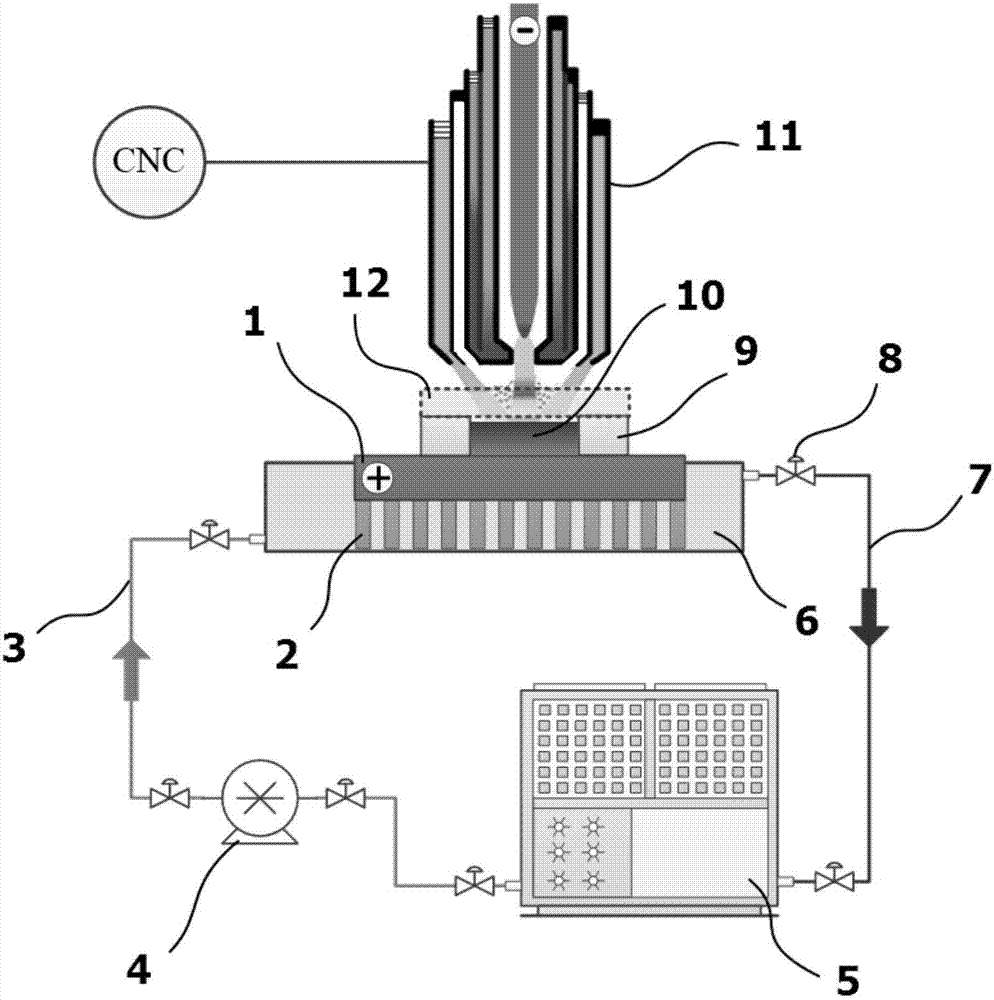
[0044] An in situ synthesized directed growth M 7 C 3 A coating preparation device, the device includes a workpiece support 2, a substrate 1 is arranged on the support 2, a coating reaction molten pool 10 is provided above the substrate 1, and ceramic insulation is provided on both sides of the coating reaction molten pool 10. plate 9, a plasma arc torch 11 is arranged above the ceramic insulation plate 9;

[0045] The bottom of the substrate 1 is provided with a cooling water tank 6, the cooling water tank 6 is connected to the water inlet pipe 3, the water inlet pipe 3 is connected to the water pump 4, the water pump 4 is connected to the refrigerator 5, and the refrigerator 5 is connected to the water outlet pipe 7 connections.

[0046] Preferably, thermal insulation ceramic fibers 12 are provided above the ceramic thermal insulation board 9 and the coating reaction molten pool 10 .

[0047] Further preferably, a valve is provided among the cooling wa...

Example Embodiment

[0048] Example 2

[0049] The device of Example 1 is used for preparation. Firstly, the surface of the substrate 1 is polished, washed with acetone, and then dried; the pretreated substrate 1 is placed on the workpiece support 2 of the cooling water tank 6, and then the valve 8, the water pump 4, and the The refrigerator 5 cools the workpiece, and bonds the thermal insulation ceramic plate 9 on the substrate according to the width and length of the coating.

[0050] 30% Cr powder (particle size 75-150μm), 5.4% C powder, and the balance Fe-Ni self-fluxing alloy powder (Ni=30%; Re=1%; Fe=69%, particle size 60- 180 μm) after drying and mixing evenly, the surface of the workpiece pre-applied between the thermal insulation ceramic plates 9 is tamped and flattened; the plasma arc gun 11 is turned on, and the process parameters are: current: 85A; voltage: 45V; ion gas flow rate: 6L / min The protective gas flow rate is: 8L / min; the CNC moving speed: 60mm / min; while the coating is prep...

Example Embodiment

[0052] Example 3

[0053] The device of Example 1 is used for preparation. Firstly, the surface of the substrate 1 is polished, washed with acetone, and then dried; the pretreated substrate 1 is placed on the workpiece support 2 of the cooling water tank 6, and then the valve 8, the water pump 4, and the The refrigerator 5 cools the workpiece, and bonds the thermal insulation ceramic plate 9 on the substrate according to the width and length of the coating.

[0054] 40% of Cr powder (particle size 75-150μm), 5.8% of C powder, and the balance of Fe-Ni self-fluxing alloy powder (Ni=30%; Re=1%; Fe=69%, particle size of 60- 180 μm) after drying and mixing evenly, the surface of the workpiece pre-applied between the thermal insulation ceramic plates 9 is tamped and flattened; the plasma arc gun 11 is turned on, and the process parameters are: current: 75A; voltage: 35-45V; ion gas flow rate: 5L / min; protective gas flow rate: 7L / min; CNC moving speed: 40mm / min; while preparing the...


PUM

PropertyMeasurementUnit
Granularityaaaaaaaaaa
Volume fractionaaaaaaaaaa

Abstract

The invention relates to the field of wear-resisting coatings, in particular to a preparing method for an in-situ synthesis oriented growth M7C3 coating. By means of the method, Cr, C and Fe-Ni powder serve as raw materials, are mixed according to a proportion and are pre-laid on a coating base plate to be rammed and flattened, and high-temperature-resisting ceramic is adopted on the two sides of a pre-laid coating for heat preservation; meanwhile, aluminum silicate ceramic fiber is used for conducting heat preservation on the part above a molten pool while the coating is prepared, and heat is prevented from being dissipated from the upper portion of the coating; and forced cooling is adopted on the bottom of the coating base plate so that heat of the molten pool can be controlled to be guided out from the bottom of the base plate from top to bottom, the temperature gradient needed by oriented growth of M7C3 is obtained, and preparing of the oriented growth M7C3 coating is achieved. Due to the fact that one-dimensional guiding-out of coating heat is achieved through the preparing method, growth of M7C3 crystals in other directions is inhibited, and the oriented growth M7C3 is obtained; and generation of columnar M7C3 crossed cracks is reduced, material toughness is improved, in addition, a column cross section with higher wear resistance is located on a work face, and wear resistance of the materials can be improved.

Description

technical field [0001] The invention relates to the field of wear-resistant coatings, in particular to an in-situ synthetic directional growth M 7 C 3 Coating preparation method. Background technique [0002] Iron-based carbide M 7 C 3 (M=Cr, Fe) reinforced material is a kind of wear-resistant material with excellent performance. It is widely used in mining, cement, thermal power generation and other industries, and has the reputation of "industrial teeth". In recent years, with the implementation of my country's "Belt and Road" strategy and the construction of major projects such as large-scale water conservancy projects, bridge projects, and high-speed railways, there is a demand for wear-resistant materials with higher wear resistance, better energy-saving effects, and lower wear increase accordingly. But when increasing M 7 C 3 When the content is used to improve the wear resistance of the material, it is found that the wear resistance does not increase but decreas...

Claims


Application Information

Patent Timeline
IPC IPC(8): C23C24/10
CPCC23C24/10
Inventor 袁有录
Owner CHINA THREE GORGES UNIV
Why Eureka
Try Eureka