Supercharge Your Innovation With Domain-Expert AI Agents!

Blowing and suction machine

A technology for blowing and suction machines and bodies, which is applied in the direction of vacuum cleaners, mechanical equipment, machines/engines, etc., which can solve problems such as inconvenient use, achieve the effects of expanding the scope of application, good versatility, and improving work efficiency

Active Publication Date: 2016-05-18
ZHEJIANG PRULDE ELECTRIC APPLIANCE CO LTD
View PDF6 Cites 1 Cited by
  • Summary
  • Abstract
  • Description
  • Claims
  • Application Information

AI Technical Summary

Problems solved by technology

[0004] For ease of use, the existing blower is generally set as a small hand-held type. The airflow direction of the blower is fixed relative to the blower when it is working. To change the airflow direction, it is necessary to adjust the blower as a whole. orientation, sometimes inconvenient to use

Method used


Image

  • Blowing and suction machine
  • Blowing and suction machine
  • Blowing and suction machine

Examples


Embodiment Construction

[0041] The present invention will be further described below in conjunction with accompanying drawing.

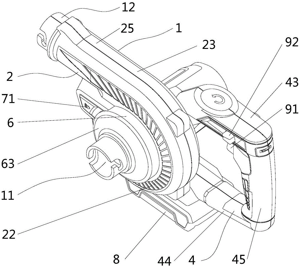
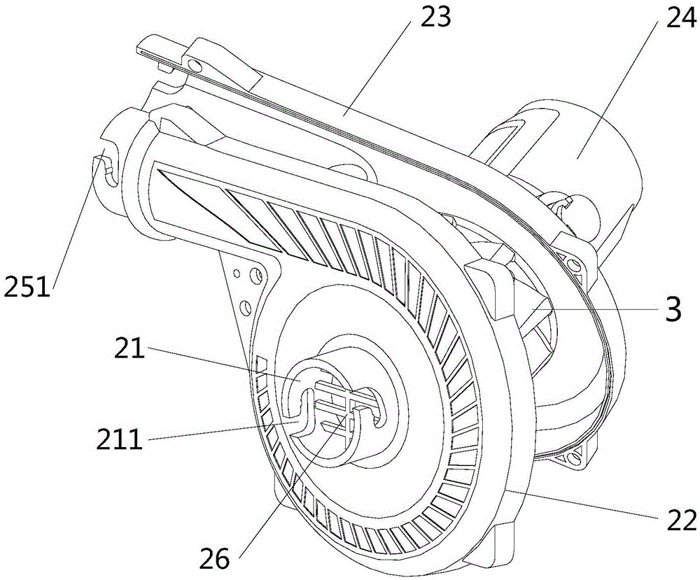
[0042] Such as figure 1 , 2As shown, the air blower provided by the embodiment of the present invention includes a body 1, a base 4 and a battery mechanism 8, the body is provided with a connected air suction port 11 and a blower port 12, the body includes a casing 2, and is located in the casing. The impeller 3 and the motor (not shown) used to drive the impeller 3 to rotate in the casing, the body 1 is arranged on the base 4 through an adjustment mechanism.

[0043] The casing 2 includes a left casing 22 and a right casing 23 which are fixedly connected together. The left casing is provided with a suction pipe 21 extending horizontally outwards from the right casing to form the suction port 11. The suction pipe is far away from the right casing. A first card slot 211 is disposed on an end of the left casing 22 . The right casing 23 is provided with a protruding portion...


PUM


Abstract

The invention discloses a blowing and suction machine, which belongs to the technical field of mechanical equipment. The blowing and suction machine comprises a machine body, wherein the machine body comprises a shell, an impeller and a motor; the impeller is arranged in the shell; the motor is arranged in the shell and used for driving the impeller to rotate; an air suction opening and an air blowing opening, which are communicated with each other, are formed in the machine body; the blowing and suction machine further comprises a base; the machine body is mounted on the base through an adjusting mechanism; the adjusting mechanism comprises a connecting piece, an adjusting button and a returning piece; the machine body is rotationally mounted on the base through the connecting piece; the adjusting button is arranged on the base and matched with the connecting piece to limit the connecting piece; and the returning piece is arranged on the base and matched with the adjusting button to drive the adjusting button to return. The invention is advantaged in that the whole structure of the blowing and suction machine is simple, the angle of the machine body relative to the base can be adjusted according to the placing position or working demands because the machine body is mounted on the base through the adjusting mechanism, the universality of the blowing and suction machine is good and the whole structure of the blowing and suction machine is compact.

Description

technical field [0001] The invention relates to the technical field of mechanical equipment, in particular to a blower and suction machine. Background technique [0002] Power tools with two functions of suction and blowing are widely used in life and work. For example, blowers in the field of garden tools are mainly used for cleaning and collecting fallen leaves. [0003] Generally, the fan of the blowing machine adopts a centrifugal fan. When the blowing machine is in the blowing mode, the high-speed airflow blown from the blowing pipe will blow and gather scattered leaves, dust, and fine debris; In air mode, the fan rotates at a high speed to form an air suction to suck leaves, dust or fine debris into the collection device to complete the cleaning. [0004] For ease of use, the existing blower is generally set as a small hand-held type. The airflow direction of the blower is fixed relative to the blower when it is working. To change the airflow direction, it is necessar...

Claims


Application Information

Patent Timeline
IPC IPC(8): E01H1/08
CPCE01H1/0863A47L5/14A47L9/2842A47L9/2857A01G20/47F04D29/4226
Inventor 韩挺杨伟明
Owner ZHEJIANG PRULDE ELECTRIC APPLIANCE CO LTD
Features
  • R&D
  • Intellectual Property
  • Life Sciences
  • Materials
  • Tech Scout
  • Unparalleled Data Quality
  • Higher Quality Content
  • 60% Fewer Hallucinations
Learn More