Main body of linear roller bearing

A kind of rolling bearing and rolling element technology, applied in the direction of linear motion bearings, bearings, bearing components, etc., can solve problems such as multiple deformation steps, and achieve the effect of uniform feed speed and high alignment accuracy

Active Publication Date: 2016-05-18
ROBERT BOSCH GMBH
View PDF13 Cites 0 Cited by
  • Summary
  • Abstract
  • Description
  • Claims
  • Application Information

AI Technical Summary

Problems solved by technology

But multiple deformation steps are required in guide parts with a U-shaped cross-section
Furthermore, it is difficult to maintain the exact distance between the two U-shaped legs, which requires reprocessing with extensive material removal

Method used


Image

  • Main body of linear roller bearing
  • Main body of linear roller bearing
  • Main body of linear roller bearing

Examples


Embodiment Construction

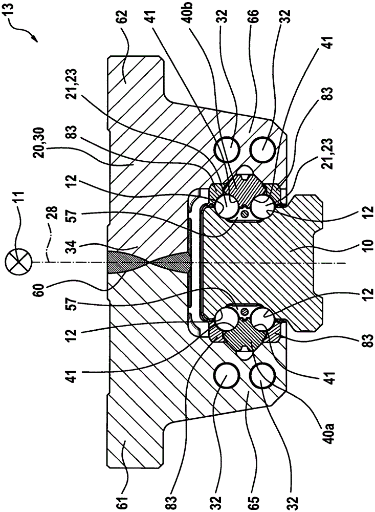
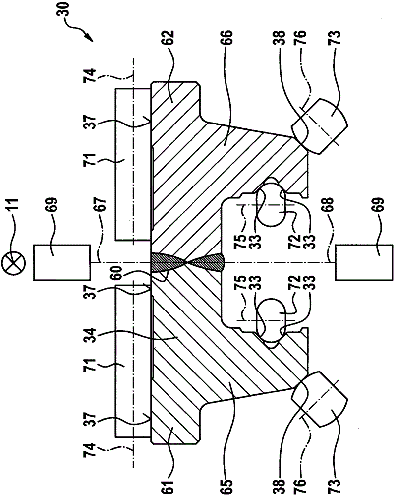
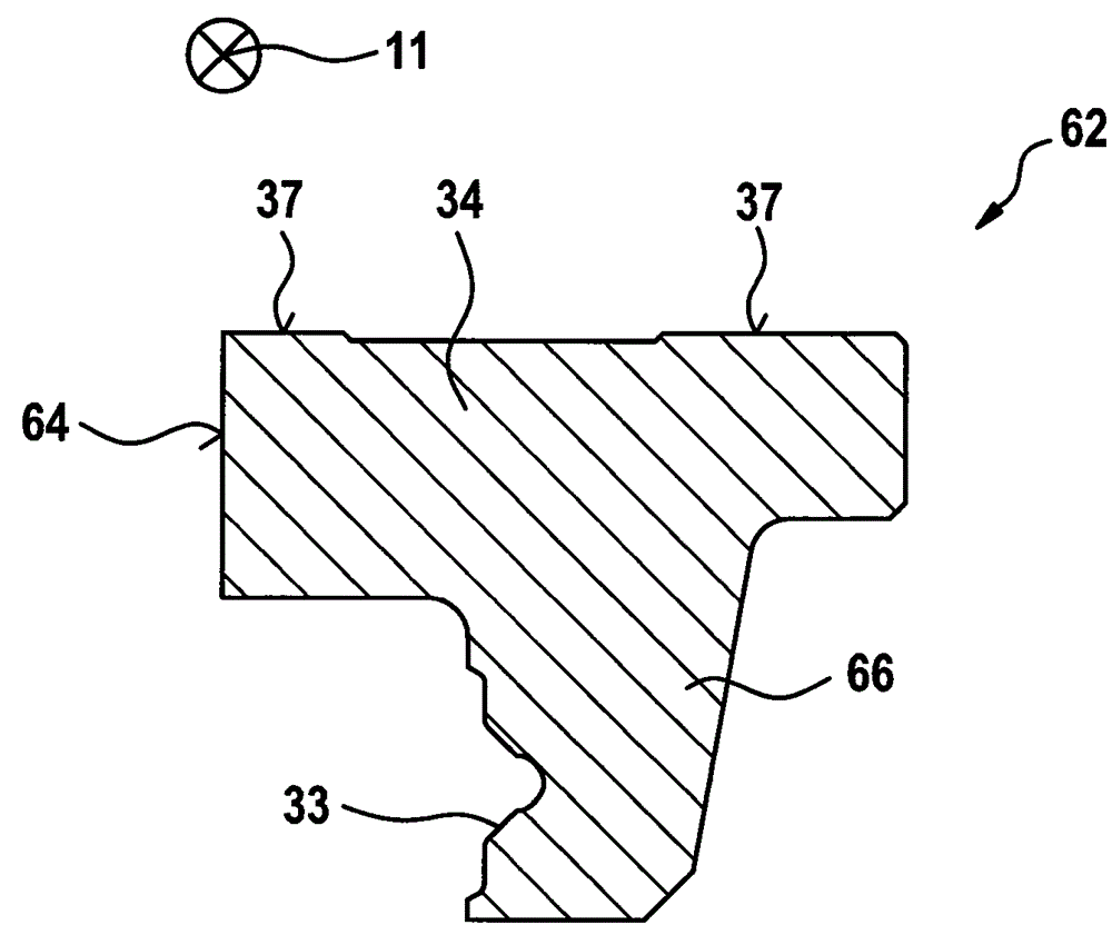
[0030] figure 1 An exploded view of the guide carriage 20 according to the invention is shown. The guide carriage 20 comprises a main body 30 made of non-hardened steel, which extends in the longitudinal direction 11 with a substantially constant U-shaped cross-sectional shape. On the inner sides of the U-shaped legs 65 ; 66 , fastening contours 33 in the form of V-grooves are arranged respectively, against which a separate running track pad 40 a ; 40 b , which is made of hardened rolling bearing steel, rests. The two running track pads 40a; 40b extend in the longitudinal direction 11 with a substantially constant cross-sectional shape, wherein they each have two carriage running tracks, whereby the guide carriage 20 has a total of four rows of rolling bodies ( figure 2 No. 21 in . The invention can also be used with guided carriages, where the carriage travel rails are located directly on the main body.

[0031] An end cap 50 , which has an inner longitudinal end face 55 ...


PUM


Abstract

The invention relates to a method for manufacturing a main body (30) of a linear roller bearing (13), which is viewed in cross section U-shape, wherein the main body has a base (34) and a first and a second U-shaped side leg; the first and the second U-shaped side leg (65; 66) are perpendicular to the base (34) and protrude from the base. According to the invention, the method comprises the following steps: a) preparing a separate first part (61) which comprises the first U-shaped leg (65) and forms a part of the base (34); b) preparing a second separate part (62) which forms the second U-shaped side leg (66) and a part of the base (34); and c) welding the first and the second part (61; 62) in the region of the base (34).

Description

technical field [0001] The invention relates to a method for machining a body of a linear rolling bearing and a guide carriage with such a body. Background technique [0002] A linear rolling bearing with a guide carriage and a longitudinally extending guide rail is known from EP449595B1. The U-shaped guide carriage is movably supported on the guide rail by a total of four continuously encircling rolling element rows. The metal body of the guide carriage consists of a total of three parts, which are bolted together. Such bodies are expensive to machine. [0003] A guide rail for linear bearings is known from EP1649180B9, which has a base body with a plurality of moving rail parts which are laser welded to the base body. [0004] Furthermore, EP1284170B1 discloses a steel profile rod for the production of linear guide components, wherein the profile rod is cold-drawn in a process step. This process is very cost-effective. However, several forming steps are required in th...

Claims


Application Information

Patent Timeline
Patent Type & Authority Applications(China)
IPC IPC(8): F16C29/04F16C33/60
CPCF16C29/0604F16C29/0645F16C2226/36
Inventor W.克劳斯R.格罗伊贝尔
Owner ROBERT BOSCH GMBH
Why Eureka
Try Eureka