Full-automatic clean heat energy recovery device

A heat energy recovery, fully automatic technology, applied in the direction of cleaning heat transfer devices, heat exchanger types, indirect heat exchangers, etc. problems, to reduce the cost of use, improve the service life, and maintain the efficiency of heat recovery.

Active Publication Date: 2016-05-18
周永伟
View PDF9 Cites 3 Cited by
  • Summary
  • Abstract
  • Description
  • Claims
  • Application Information

AI Technical Summary

Problems solved by technology

[0004] The sewage heat energy utilization device with this structure can recover the heat energy in the sewage, but at the same time, because the waste water for recovering heat energy is usually industrial wastewater or domestic waste water, after long-term use, it will cause blockage in the heat energy utilization device and a lot of dust inside the device. Stain deposition affects heat exchange efficiency, so generally the heat recovery device is basically a detachable structure, which needs to be replaced after a period of use, which makes the use of heat recovery devices by factories or businesses to save heat but also increase the cost of use
[0005] To sum up, the heat energy recovery device in the prior art currently has a high cost of use due to the inability to automatically clean or the poor automatic cleaning effect

Method used


Image

  • Full-automatic clean heat energy recovery device
  • Full-automatic clean heat energy recovery device
  • Full-automatic clean heat energy recovery device

Examples


Embodiment Construction

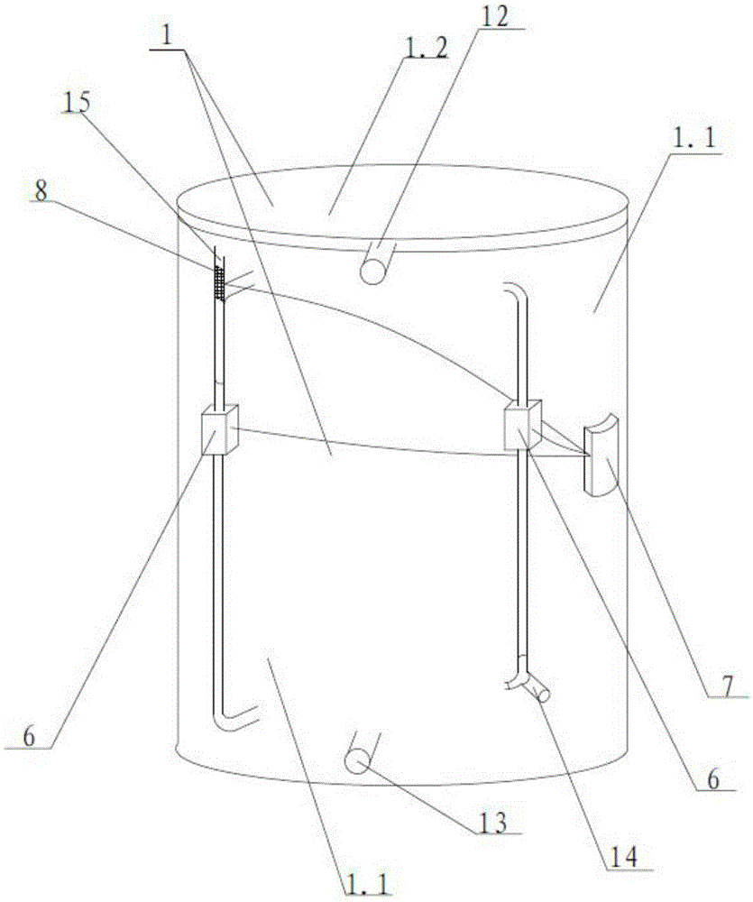
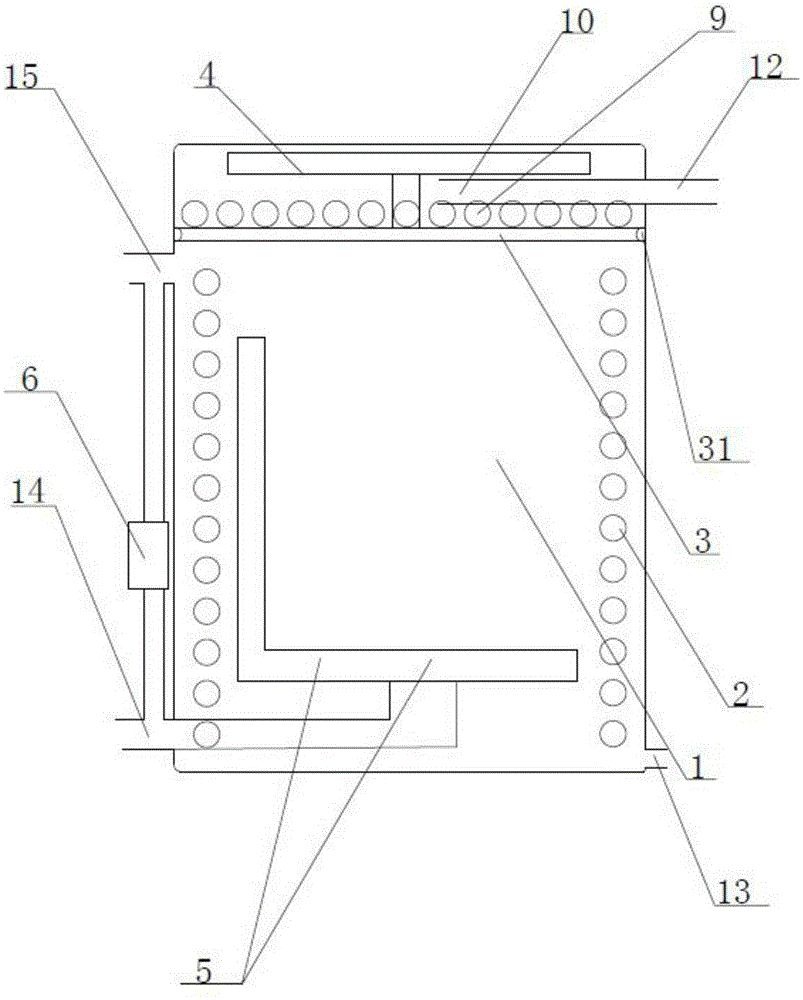
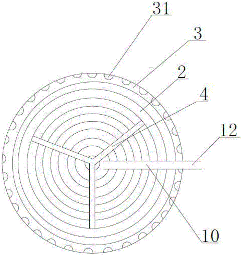
[0013] According to attached Figures 1 to 3 As described above, a fully automatic cleaning heat energy recovery device includes a barrel body, the barrel body is provided with a hot water inlet, a hot water outlet, a cold water inlet and a cold water outlet, and the barrel body is provided with a coiled incense bellows and a spiral type bellows, the incense-type bellows and the spiral bellows constitute an energy-saving inner core, the upper part of the energy-saving inner core is provided with a water guide plate 3, and the water guide plate is provided with a water guide hole, and the guide A 360° plane rotating nozzle is arranged above the water plate, and a 360° three-dimensional rotating cleaning nozzle is arranged in the barrel body. The lower part is connected with the barrel body, the cold water inlet is connected with the spiral bellows, the cold water outlet is connected with the coiled bellows, and the cold water inlet is also connected with the 360° plane rotating...


PUM


Abstract

The invention relates to the technical field of renewable energy, in particular to a full-automatic clean heat energy recovery device. The interior structure of the full-automatic clean heat energy recovery device can be cleaned automatically, the full-automatic clean heat energy recovery device is prevented from being blocked, and thus the full-automatic clean heat energy recovery device can be used for a long time without being replaced. The full-automatic clean heat energy recovery device comprises a bucket body. A hot water inlet, a hot water outlet, a cold water inlet and a cold water outlet are formed in the bucket body. Incense coil type corrugated pipes and spiral type corrugated pipes are arranged in the bucket body. An energy-saving inner core is formed by the incense coil type corrugated pipes and the spiral type corrugated pipes. A water guide plate is arranged on the upper portion of the energy-saving inner core. A planar rotary spray head is arranged above the water guide plate. A three-dimensional rotary cleaning spray head is arranged in the bucket body. The hot water inlet is formed in the upper portion of the bucket body. The hot water outlet is formed in the lower portion of the bucket body. The cold water inlet communicates with the spiral type corrugated pipes. The cold water outlet communicates with the incense coil type corrugated pipes. The cold water inlet also communicates with the planar rotary spray head, and an electromagnetic valve is arranged on the passageway between the cold water inlet and the planar rotary spray head. The cold water outlet also communicates with the three-dimensional rotary cleaning spray head through a tee joint, and an electromagnetic valve is further arranged on the passageway between the cold water outlet and the three-dimensional rotary cleaning spray head. The full-automatic clean heat energy recovery device further comprises an electric controller, wherein the electric controller is installed on the bucket body and electrically connected with the electromagnetic valves.

Description

technical field [0001] The invention relates to the technical field of renewable energy, in particular to a fully automatic cleaning heat recovery device. Background technique [0002] At present, the heat energy recovery device in the prior art is mainly aimed at the heat energy recovery of domestic or industrial waste hot water, and adopts the principle of cold and hot water heat exchange. And the cold water pipe from bottom to top, through the contact between cold and hot water, the cold water is heated up, and then the heat energy in the waste hot water is recovered. [0003] For example, the Chinese patent CN101929809B which adopts this principle discloses a sewage heat utilization device. The specific structure is like a hot water treatment device, which contains a thermal insulation box. The box is divided into two layers. It is connected to the hot water sewer pipe, and the lower layer is sealed with a pressure-resistant heating insulation layer. The bottom of the p...

Claims


Application Information

Patent Timeline
Patent Type & Authority Applications(China)
IPC IPC(8): F28D7/02F28G9/00
CPCF28D7/024F28G9/00
Inventor 周永伟
Owner 周永伟
Why Eureka
Try Eureka