
A liquid distillation condensing device

A distillation condensing device and liquid technology, applied in distillation separation, vapor condensation, reflux condensation, etc., can solve the problems of inconvenient removal of distillation bottles, low space utilization, easy bumping and scratching, etc., to ensure circulating cooling. effect, increase efficiency and effectiveness, avoid the effect of retort contamination

Active Publication Date: 2017-08-11
JINAN SENTE ELECTRONICS TECH
View PDF6 Cites 0 Cited by
  • Summary
  • Abstract
  • Description
  • Claims
  • Application Information

AI Technical Summary

Problems solved by technology

[0002] In the liquid distillation and condensing devices in the prior art, such as water distillation devices, the condensing structure is installed on the upper part of the distillation bottle and fixed and supported by a special support frame, which requires an external cooling circulation pump to circulate and cool, and has a heavy mass, a high center of gravity, and a large shape , the overall stability is poor, easy to bump and scratch, storage and transportation are inconvenient
Since the top of the retort is connected to the bottom of the condensing structure, and the condensing structure is fixedly supported on the fixed shell, the retort is inconvenient to remove, and it is easy to be bumped and scratched when it is removed. Generally, professional operators are required to install and disassemble it.
The condensing structure, especially the inside of the condensing pipe, is not easy to clean after long-term use. The high-temperature and high-pressure structure has poor safety protection and is prone to safety hazards. In addition, due to the complex structure of the whole machine, it occupies a relatively large space and the space utilization rate is low.

Method used


Image

  • A liquid distillation condensing device
  • A liquid distillation condensing device
  • A liquid distillation condensing device

Examples


Embodiment Construction

[0018] In order to better understand the present invention, the implementation manner of the present invention will be explained in detail below in conjunction with the accompanying drawings.

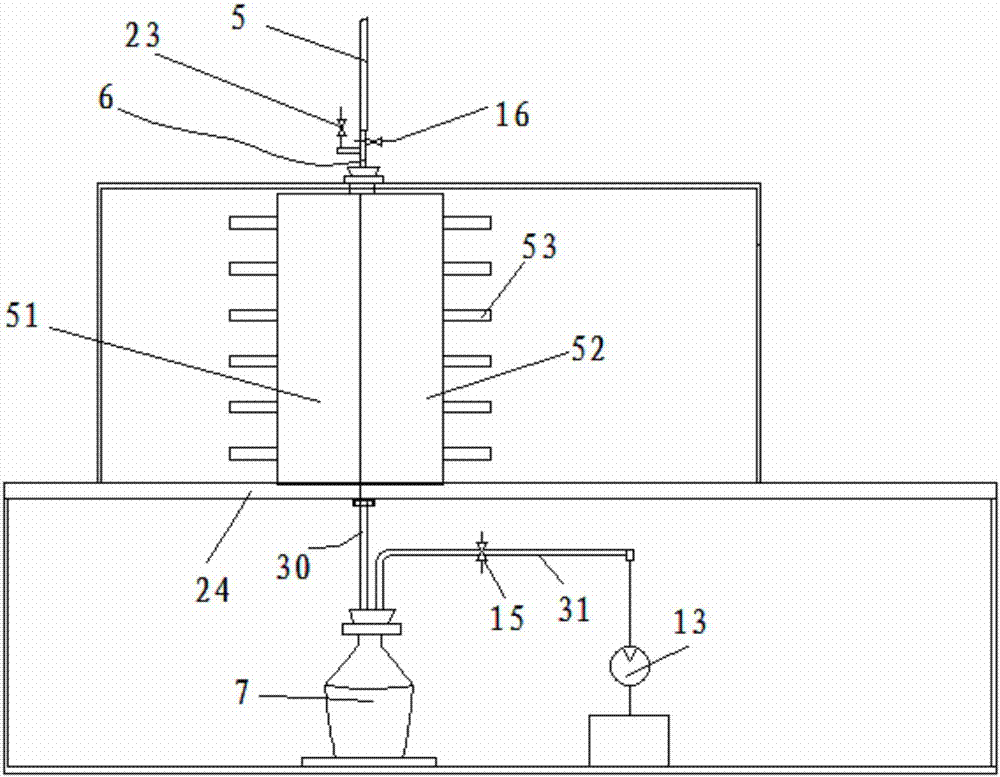
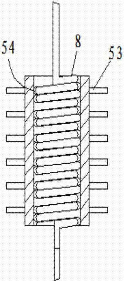
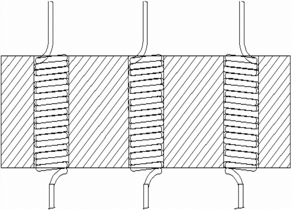
[0019] combine Figure 1 to Figure 3 , a liquid distillation condensing device, comprising a condensing sleeve, the condensing sleeve is supported on the housing 24 at the bottom of the retort, the upper end of the spiral condensing tube 8 is connected to the lower end of the conduit through a valve 6, and the upper end of the conduit 5 is connected to the retort The gas outlet is connected, the lower end of the spiral condensing tube is connected with the reflux bottle 7, the reflux bottle 7 is arranged at the lower part of the housing, the mouth of the reflux bottle 7 is provided with an air outlet pipe, 31, and the outlet pipe is connected with the negative pressure pump 13, An on-off valve 3 15 is provided on the outlet pipe, and the condensation sleeve is provided with an inner hol...


PUM


Abstract

The invention discloses a liquid distillation condensing device. The condensing device comprises a condensing casing pipe supported on an intermediate housing body; the upper end of each spiral condenser pipe is connected to the lower end of a pipe via a valve; the upper end of the pipe is connected to the outlet of a distilling flask; the lower ends of the spiral condenser pipes are connected to reflux bottles; the reflux bottles are arranged on the lower part of the housing body; the mouth of each reflux bottles is provided with a vent pipe; the vent pipes are connected with a vacuum pump; an on-off valve 3 is arranged on each vent pipe; the condensing casing pipe is provided with inner holes; the wall of each inner hole is provided with a PTFE coating; each inner hole is provided with a spiral groove cooperating with the spiral condenser pipe; the spiral condenser pipes are embedded into the spiral grooves; the condensing casing pipe includes a semi-cylindrical ring 1 and a semi-cylindrical ring 2; and the spiral grooves are respectively arranged in the inner walls of the two semi-cylindrical rings. The device has a simple structure, and reliable heat radiation and cooling, does not need additional cooling cycle power, and has remarkable energy-saving effect.

Description

technical field [0001] The invention relates to the technical field of distillation equipment, in particular to a liquid distillation condensing device. Background technique [0002] In the liquid distillation and condensing devices in the prior art, such as water distillation devices, the condensing structure is installed on the upper part of the distillation bottle and fixed and supported by a special support frame, which requires an external cooling circulation pump to circulate and cool, and has a heavy mass, a high center of gravity, and a large shape , The overall stability is poor, it is easy to bump and scratch, and it is inconvenient to store and transport. Since the top of the retort is connected to the bottom of the condensing structure, and the condensing structure is fixedly supported on the fixed shell, the retort is inconvenient to remove, and it is easy to be bumped and scratched when it is removed. Generally, professional operators are required to install an...

Claims


Application Information

Patent Timeline
Patent Type & Authority Patents(China)
IPC IPC(8): B01D3/00B01D5/00B01L3/16
CPCB01D5/0006B01D5/0063B01L3/16
Inventor 段作敏向晓黎张户勇
Owner JINAN SENTE ELECTRONICS TECH
Learn More