Gas distribution device

A technology of gas distribution device and distribution plate, which is applied in the field of wind and gas exhaust, and can solve problems such as difficult to enlarge design and application, difficult to ensure uniform distribution of gas, complex structure, etc.

Inactive Publication Date: 2016-05-25
BEIJING UNIV OF CHEM TECH
View PDF4 Cites 9 Cited by
  • Summary
  • Abstract
  • Description
  • Claims
  • Application Information

AI Technical Summary

Problems solved by technology

The disadvantage of this device is that the structure is complex and heavy, and it is difficult to ensure the effect of uniform gas distribution; and from the structure, it is not clear how the wind exhaust gas gathers on the small section of the inlet, how to quickly disperse and evenly along the section after entering the oxidation device distribution; the patent only gives the implementation scheme on the 500×600mm cross-section, which is difficult to scale up and apply to large-scale oxidation devices

Method used


Image

  • Gas distribution device

Examples


Embodiment 1

[0028] The processing capacity is 1000m 3 The inlet and outlet of the catalytic oxidation device for air exhaust gas / min are respectively equipped with combined gas distribution devices. The cross-sectional size of the oxidation device is 6000mm×6000mm, the catalyst is a monolithic noble metal catalyst loaded with 0.5% Pd, the carrier is a 200-mesh cordierite honeycomb ceramic, and the heat storage ceramic is a corundum-mullite honeycomb ceramic. The data acquisition and control of the device is completed by Siemens S7-300PLC, and the upper computer has a perfect man-machine interface.

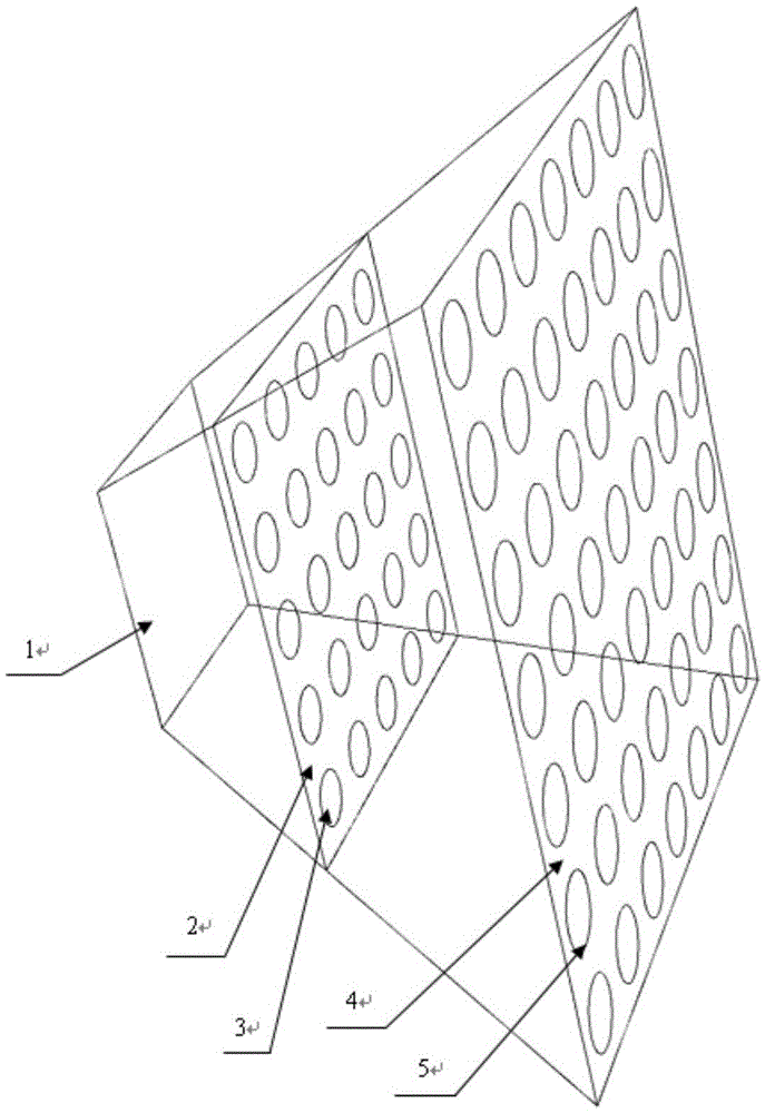
[0029] The structure of the transition section in the gas distribution device in this embodiment is as follows figure 1 As shown, the cross-sectional area of ​​the gas inlet is 2m 2 , the cross-sectional area of ​​the gas outlet is 24m 2, there are two distribution plates in the transition section, the distance between the first distribution plate closest to the inlet of the gas distributio...


PUM


Abstract

The invention provides a gas distribution device which comprises a transition section and distribution plates, wherein the transition section is provided with a gas inlet and a gas outlet; the transition section is internally provided with one distribution plate or a plurality of distribution plates arranged at intervals; the plurality of distribution plates arranged at intervals are sequentially distributed in a direction from the gas inlet to the gas outlet; the edge of each distribution plate is connected with an inner wall of the transition section; the distribution plates are provided with a plurality of through holes; windblown mine gas enters into the gas distribution device through the inlet of the gas distribution device; the on-way resistance of the windblown mine gas along the cross section can be preliminarily adjusted by use of the through hole in the distribution plate adjacent to the gas inlet section; then the windblown mine gas enters into the through holes in the other distribution plates, so that the on-way resistance of the windblown mine gas along the cross section can be adjusted again, the flow velocity of the gas along the cross section of the gas distribution device is uniform, and thus the purpose of enabling the gas to enter an oxidation device so as to flow uniformly is achieved.

Description

technical field [0001] The invention relates to the technical field of wind exhaust gas, in particular to a gas distribution device. Background technique [0002] Every year, the methane emitted by wind and gas exhaust from coal mines in China is about 20 billion cubic meters. Due to the low concentration of methane in wind exhaust gas, it cannot be ignited by conventional methods. Therefore, wind exhaust gas has not been effectively utilized for a long time, but is directly discharged into the atmosphere. [0003] The regenerative oxidation method is to maintain the temperature required for oxidation by accumulating the heat released after the oxidation of methane in the wind exhaust gas in the flow direction shift reactor, so that methane can be continuously oxidized. After oxidation, the heat can be used for heating or steam generation. This method not only reduces greenhouse gas emissions, but also uses the wasted gas as a clean resource. [0004] Regardless of the th...

Claims


Application Information

Patent Timeline
Patent Type & Authority Applications(China)
IPC IPC(8): B01J19/32B01J12/00
CPCB01J19/32B01J12/007B01J2219/32244B01J2219/32262B01J2219/32293
Inventor 贾志刚张照黄敬敬刘翻艳高娟刘欢
Owner BEIJING UNIV OF CHEM TECH
Why Eureka
Try Eureka