Glue cutter unit with interchangeable inserts

A knife device and cutting knife technology, applied in metal processing and other directions, can solve the problems of easy sliding, transfer, unstable transportation, affecting the use of the cutting knife, etc.

Active Publication Date: 2018-11-20
JIANGSU JWC MACHINERY
View PDF6 Cites 0 Cited by
  • Summary
  • Abstract
  • Description
  • Claims
  • Application Information

AI Technical Summary

Problems solved by technology

[0002] As we all know, due to the large difference in the width of the adhesive material in diaper products, when the adhesive material is transported to the bed knife roller, the material cannot completely cover the negative pressure hole on the bed knife roller. It is continuous, so as long as it cannot be fully covered, it will cause negative pressure leakage, and the pulling force on both sides of the material will become uneven, which will cause unstable transportation and transfer, and will move. Further cause the bonding between the adhesive material and the main material to be unstable, and the bonding position is also inaccurate, resulting in a large number of waste products, thereby limiting the production speed of the whole machine, reducing the pass rate of the product, and affecting the efficiency. Long-term use will stick material particles on the blade, which will affect the use of the cutter. At the same time, there will be material particles on the surface of the bed knife roller, which will not only affect the operation of the negative pressure system, but also make it easier for the material to slide on the surface of the bed knife roller. The overall operation of the equipment is not very stable

Method used


Image

  • Glue cutter unit with interchangeable inserts
  • Glue cutter unit with interchangeable inserts
  • Glue cutter unit with interchangeable inserts

Examples


Embodiment Construction

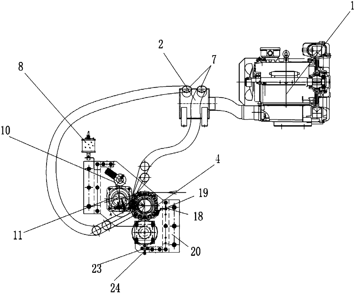
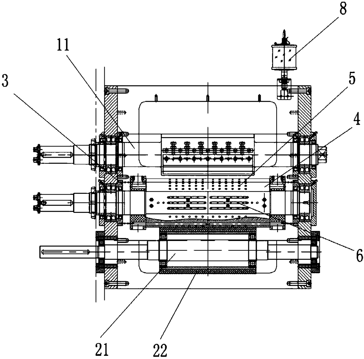
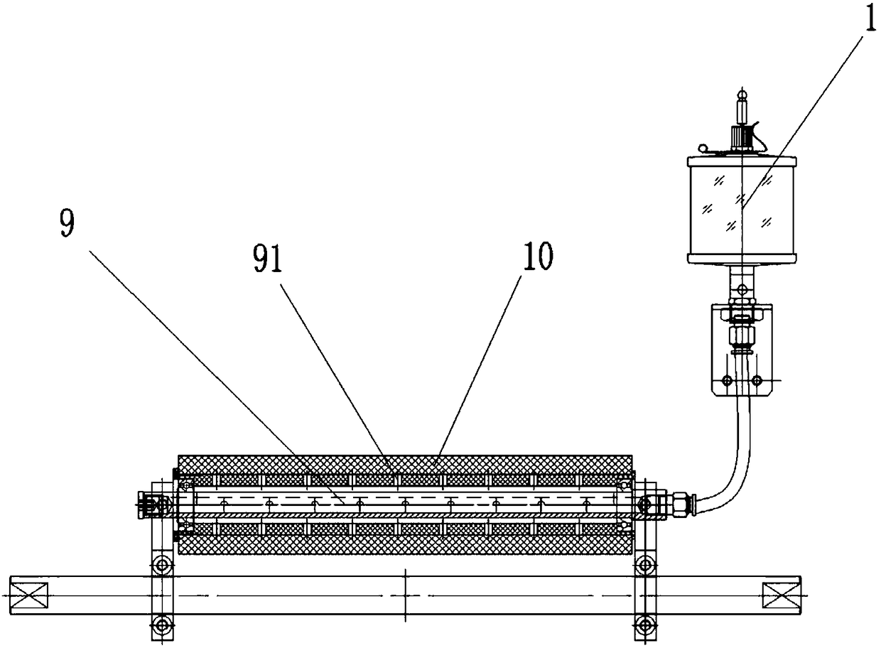
[0021] reference figure 1 , figure 2 , image 3 , Figure 4 , Figure 5 It can be seen that the adhesive cutter device with interchangeable inserts of the present invention includes a cutter system, a bottom knife roll system, a negative pressure system, and a cam bonding system. The negative pressure system includes a vortex air pump 1, a negative pressure box 2, and a negative pressure system. The pressure plate 3, the bottom knife roller system includes a bottom roller 4, on the bottom roller 4 there are two sets of negative pressure holes 5 symmetrical to the bottom roller 4, the bottom roller 4 between the two sets of negative pressure holes 5 forms a positioning surface, A set of raised positioning posts 6 are provided on the positioning surface. The negative pressure hole 5 is connected with the negative pressure plate 3. The negative pressure box 2 is provided with two negative pressure ports 7, and the negative pressure port 7 and the negative pressure plate 3 pass thr...


PUM


Abstract

The invention relates to disposable sanitary production line equipment, in particular to an adhesive tape cutter device with inserts interchangeable. Two groups of negative pressure holes are formed in a bottom roller and are symmetrical relative to the bottom roller, a locating face is formed on the part, between the two groups of negative pressure holes, of the bottom roller, a group of protruding locating pillars are arranged on the locating face, the negative pressure holes are communicated with a negative pressure plate, a negative pressure box is provided with two negative pressure openings, the negative pressure openings are connected with the negative pressure plate through negative pressure pipes, and a cutter system and a cam bonding system correspond to one group of negative pressure holes respectively. According to the structure of the adhesive tape cutter device, the bottom roller is provided with double negative-pressure suction structures, the locating pillars are arranged between the two groups of negative pressure holes, in the material conveying process, even if the negative pressure holes are not covered, materials cannot be subjected to sliding or displacement on the bottom roller under the action of the locating pillars, the areas of the negative pressure holes are decreased, and power of a vortex air pump can be reduced.

Description

Technical field [0001] The invention relates to a production line equipment for disposable sanitary products, in particular to a glue cutting knife device with interchangeable inserts. Background technique [0002] As we all know, due to the large difference in the width of the adhesive tape in diaper products, when the adhesive tape material is conveyed to the bed knife roller, the material cannot completely cover the negative pressure hole on the bed knife roller. It is continuous, so as long as it cannot cover all of it, it will cause the leakage of negative pressure, and the pulling force on both sides of the material will become uneven, which will cause the defects of unstable transportation and migration; after cutting, the transfer and transportation are unstable, thus Furthermore, the bonding between the adhesive material and the main material is unstable, and the bonding position is also inaccurate, resulting in a large amount of waste, which limits the production speed ...

Claims


Application Information

Patent Timeline
Patent Type & Authority Patents(China)
IPC IPC(8): B26D7/01B26D7/08B26D7/26B26D7/18
CPCB26D7/01B26D7/018B26D7/088B26D7/18B26D7/2614B26D7/2628
Inventor 宋潇潇陈斌熊平
Owner JIANGSU JWC MACHINERY
Why Eureka
Try Eureka