Supercharge Your Innovation With Domain-Expert AI Agents!

Electronic device, physical quantity sensor, pressure sensor and altimeter

A technology of electronic devices and sensor elements, applied in the field of moving objects, can solve problems such as cracks on the top

Inactive Publication Date: 2016-05-25
SEIKO EPSON CORP
View PDF8 Cites 3 Cited by
  • Summary
  • Abstract
  • Description
  • Claims
  • Application Information

AI Technical Summary

Problems solved by technology

[0003] However, in the MEMS element related to Patent Document 1, since the inner periphery of the space wall (side wall) has a rectangular shape corresponding to the plan view shape of the diaphragm in plan view, thermal contraction occurs at the top of the space wall. Isochronic stress concentrates on the portion of the top corresponding to the corner of the side wall, and as a result, there is a problem that damage such as cracks occurs in the top

Method used


Image

  • Electronic device, physical quantity sensor, pressure sensor and altimeter
  • Electronic device, physical quantity sensor, pressure sensor and altimeter
  • Electronic device, physical quantity sensor, pressure sensor and altimeter

Examples


no. 1 approach

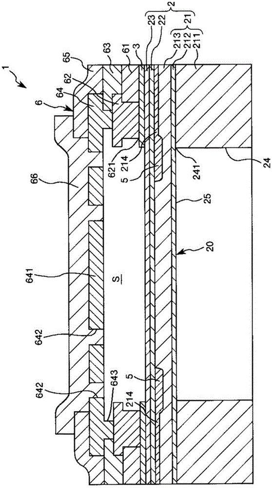
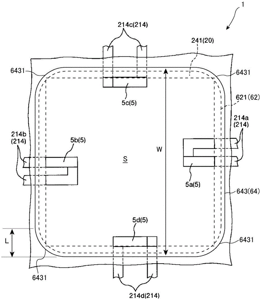
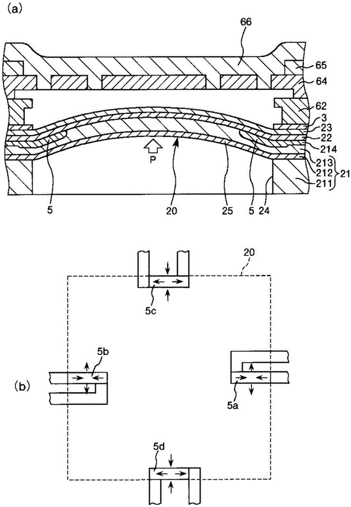
[0061] figure 1 It is a sectional view showing the physical quantity sensor according to the first embodiment of the present invention, figure 2 to represent figure 1 It is a plan view of the arrangement of piezoresistive elements (sensor elements) and walls of the shown physical quantity sensor. image 3 for the figure 1 A diagram illustrating the role of the physical quantity sensor shown, image 3 (a) is a sectional view showing a pressurized state, image 3 (b) is a plan view showing a pressurized state. In addition, in the following, for the convenience of explanation, the figure 1 The upper side is called "upper" and the lower side is called "lower".

[0062] figure 1The shown physical quantity sensor 1 includes: a substrate 2 having a diaphragm portion 20; a plurality of piezoresistive elements 5 (sensor elements) as functional elements arranged on the diaphragm portion 20; chamber) stacked structure 6; and the intermediate layer 3 arranged between the substrat...

no. 2 approach

[0138] Next, a second embodiment of the present invention will be described.

[0139] Figure 6 It is a plan view showing the arrangement of piezoresistive elements (sensor elements) and wall portions of the physical quantity sensor according to the second embodiment of the present invention.

[0140] Hereinafter, although the second embodiment of the present invention will be described, the differences from the above-mentioned embodiment will be mainly described, and the description of the same matters will be omitted.

[0141] This embodiment is the same as the first embodiment described above except that the shapes of the wall and the top are different.

[0142] Figure 6 The illustrated physical quantity sensor 1A includes wiring layers 62A and 64A, and the covering layer (not shown) of the wiring layer 64A constitutes a "top". The structure formed by the layer 64A constitutes a "wall".

[0143] Furthermore, the inner peripheral edge 643A of the end portion of the wall...

no. 3 approach

[0149] Next, a third embodiment of the present invention will be described.

[0150] Figure 7 It is a plan view showing the arrangement of piezoresistive elements (sensor elements) and wall portions of the physical quantity sensor according to the third embodiment of the present invention.

[0151] Hereinafter, although the third embodiment of the present invention will be described, the differences from the above-mentioned embodiment will be mainly described, and the description of the same matters will be omitted.

[0152] This embodiment is the same as the first embodiment described above except that the shapes of the wall and the top are different.

[0153] Figure 7 The illustrated physical quantity sensor 1B includes wiring layers 62B and 64B, and the covering layer (not shown) of the wiring layer 64B constitutes a "top". The structure formed by 64B constitutes a "wall".

[0154] In addition, the inner peripheral edge 643B of the end portion of the wall portion oppo...


PUM


Abstract

The invention provides an electronic device, a physical quantity sensor, a pressure sensor and an altimeter. The electronic device and the physical quantity sensor have excellent reliability; in addition, provided are the pressure sensor, the altimeter, the electronic device and a mobile device possess the electric device. A physical quantity sensor (1) includes a substrate, a piezoelectric resistive element (5) that is disposed on one surface side of the substrate, a wall portion that is disposed on the one surface side of the substrate so as to surround the piezoelectric resistive element (5) in a plan view of the substrate, and a ceiling portion that is disposed on an opposite side to the substrate with respect to the wall portion and forms a cavity (S) along with the wall portion, in which an inner circumferential edge (643) of an end portion of the wall portion on an opposite side to the substrate includes curved portions (6431) which are curved in the plan view.

Description

technical field [0001] The present invention relates to an electronic device, a physical quantity sensor, a pressure sensor, an altimeter, electronic equipment, and a mobile body. Background technique [0002] There is known an electronic device having a cavity formed using a semiconductor manufacturing process (for example, refer to Patent Document 1). As an example of such an electronic device, for example, a MEMS (MicroElectroMechanicalSystem: microelectromechanical system) element related to Patent Document 1 can be cited. The MEMS element has a substrate, a resonator formed on the main surface of the substrate, and a A space wall portion of a space for accommodating the resonator is also formed on the main surface of the substrate. In addition, a part of the substrate of the MEMS element according to Patent Document 1 is formed thin and functions as a diaphragm. Furthermore, the pressure is detected from the change in the frequency characteristic of the resonator acco...

Claims


Application Information

Patent Timeline
Patent Type & Authority Applications(China)
IPC IPC(8): B81B3/00G01C5/06G01L9/00
CPCB81B3/0072G01C5/06G01L9/0052G01L9/005G01L9/0048G01L9/0054
Inventor 田中信幸
Owner SEIKO EPSON CORP
Features
  • R&D
  • Intellectual Property
  • Life Sciences
  • Materials
  • Tech Scout
  • Unparalleled Data Quality
  • Higher Quality Content
  • 60% Fewer Hallucinations
Learn More