Fuel tank heating structure

A technology for heating structures and fuel tanks, applied to fuel heat treatment devices, engine components, machines/engines, etc., can solve problems such as increased maintenance probability, reduced service life of oil pipelines, blockage of diesel engine oil passages, etc., to reduce maintenance probability and prolong service life The effect of low life and heating cost

Inactive Publication Date: 2016-05-25
JIANGSU XINHAI SCI & TECH DEV CO LTD
View PDF0 Cites 4 Cited by
  • Summary
  • Abstract
  • Description
  • Claims
  • Application Information

AI Technical Summary

Problems solved by technology

[0002] The application range of diesel engine is very wide. It can be used in automobiles and other fields. Although there are various brands of low-temperature diesel oil suitable for low-temperature use on the market, in normal operation of the vehicle, if the temperature drops sharply in a short period of time, it often causes the It is too late for people to change the oil. At this time, the diesel engine is often due to the inappropriate grade of diesel oil, and the diesel oil precipitates paraffin at low temperature, which leads to the blockage of the oil circuit of the diesel engine and the failure or directly causes the engine to stall. This situation often causes troubles and losses to people in different degrees. At the same time, the oil pipeline of the existing diesel engine oil tank often does not get enough insulation measures during the use process, and it is easy to cause the service life of the oil pipeline to decrease in the high cold and low temperature area, which increases the probability of maintenance

Method used


Image

  • Fuel tank heating structure

Examples


Embodiment Construction

[0008] The specific content of the present invention will be described in detail below in conjunction with the accompanying drawings and specific embodiments.

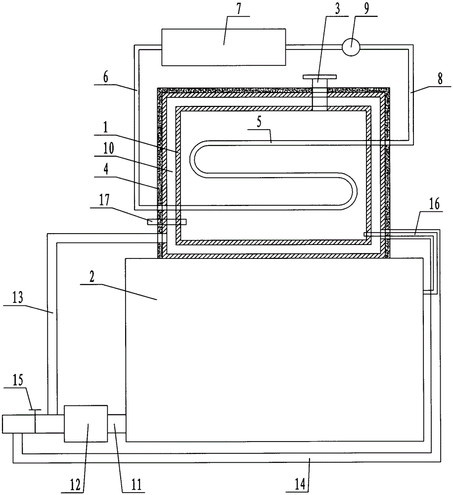
[0009] Such as figure 1 As shown, the fuel tank heating structure includes: a main fuel tank body 1, the main fuel tank body 1 is arranged on a diesel engine 2, an oil filling port 3 is arranged on the upper end of the main fuel tank body 1, and an oil filling port 3 is arranged on the outside of the main fuel tank body 1 An insulation layer 4 is provided, and an S-shaped heating water pipe 5 is arranged in the main oil tank body 1. One end of the heating water pipe 5 is connected to the circulating cooling water tank 7 through the water inlet pipe 6, and the other end of the heating water pipe 5 is passed through The return pipe 8 is connected with the circulating cooling water tank 7, a water pump 9 is arranged on the return pipe 8, a heating chamber 10 is arranged on the main oil tank body 1, and an exhaust pipe 11 ...


PUM


Abstract

The invention discloses a fuel tank heating structure with a good heating effect. The fuel tank heating structure comprises a main fuel tank body, wherein the main fuel tank body is arranged on a diesel engine, an oil injection port is formed in the upper end of the main fuel tank body, a heat insulation layer is arranged on the outer side of the main fuel tank body, an S-shaped heating water pipe is arranged in the main fuel tank body, one end of the heating water pipe is connected with a circulating cooling water tank through a water inlet pipe, and the other end of the heating water pipe is connected with the circulating cooling water tank through a water return pipe; a water suction pump is arranged on the water return pipe, and a heating chamber is arranged on the main fuel tank body; an exhaust pipe is arranged on the diesel engine, a tail gas treatment device is arranged on the exhaust pipe, an air inlet pipe is arranged on the exhaust pipe at the rear end of the tail gas treatment device, the air inlet pipe is communicated with one side of the heating chamber, and an air return pipe is arranged on the exhaust pipe at the rear end of the air inlet pipe.

Description

technical field [0001] The invention relates to a diesel engine accessory, in particular to a fuel tank heating structure. Background technique [0002] The application range of diesel engine is very wide. It can be used in automobiles and other fields. Although there are various brands of low-temperature diesel oil suitable for low-temperature use on the market, in normal operation of the vehicle, if the temperature drops sharply in a short period of time, it often causes the It is too late for people to change the oil. At this time, the diesel engine is often due to the inappropriate grade of diesel oil, and the diesel oil precipitates paraffin at low temperature, which leads to the blockage of the oil circuit of the diesel engine and the failure or directly causes the engine to stall. This situation often causes troubles and losses to people in different degrees. , At the same time, the existing diesel engine oil tank often does not get enough insulation measures for the ...

Claims


Application Information

Patent Timeline
Patent Type & Authority Applications(China)
IPC IPC(8): F02M31/16
CPCF02M31/16
Inventor 徐海山周锦祥许保发黄长勇徐文杰
Owner JIANGSU XINHAI SCI & TECH DEV CO LTD
Why Eureka
Try Eureka