
Coal gas pressurizing machine

A pressurizer and gas technology, applied in the direction of mechanical equipment, machines/engines, liquid fuel engines, etc., can solve problems affecting the safe operation of fans, gas leakage, etc., and achieve ingenious design and installation, high air tightness, and improved efficiency Effect

Active Publication Date: 2016-05-25
JIN TONG LING TECH GRP CO LTD
View PDF8 Cites 8 Cited by
  • Summary
  • Abstract
  • Description
  • Claims
  • Application Information

AI Technical Summary

Problems solved by technology

[0005] In order to overcome the problem in the prior art that the gas pressurizer often encounters a large flow of gas for pressurization during the application process, the gas leaks and affects the safe operation of the fan, the present invention provides a gas pressurizer

Method used


Image

  • Coal gas pressurizing machine
  • Coal gas pressurizing machine
  • Coal gas pressurizing machine

Examples


Embodiment Construction

[0027] The present invention will be further described in detail below with reference to the accompanying drawings and embodiments. It should be understood that the specific embodiments described herein are only used to explain the present invention, but not to limit the present invention.

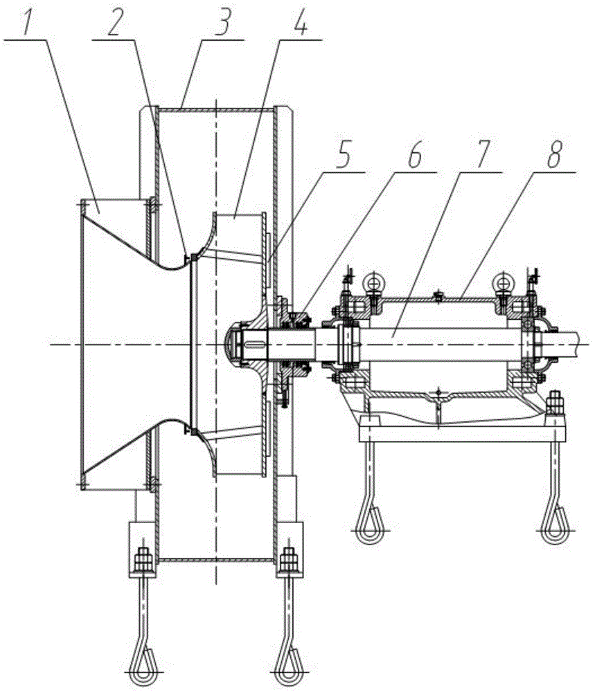
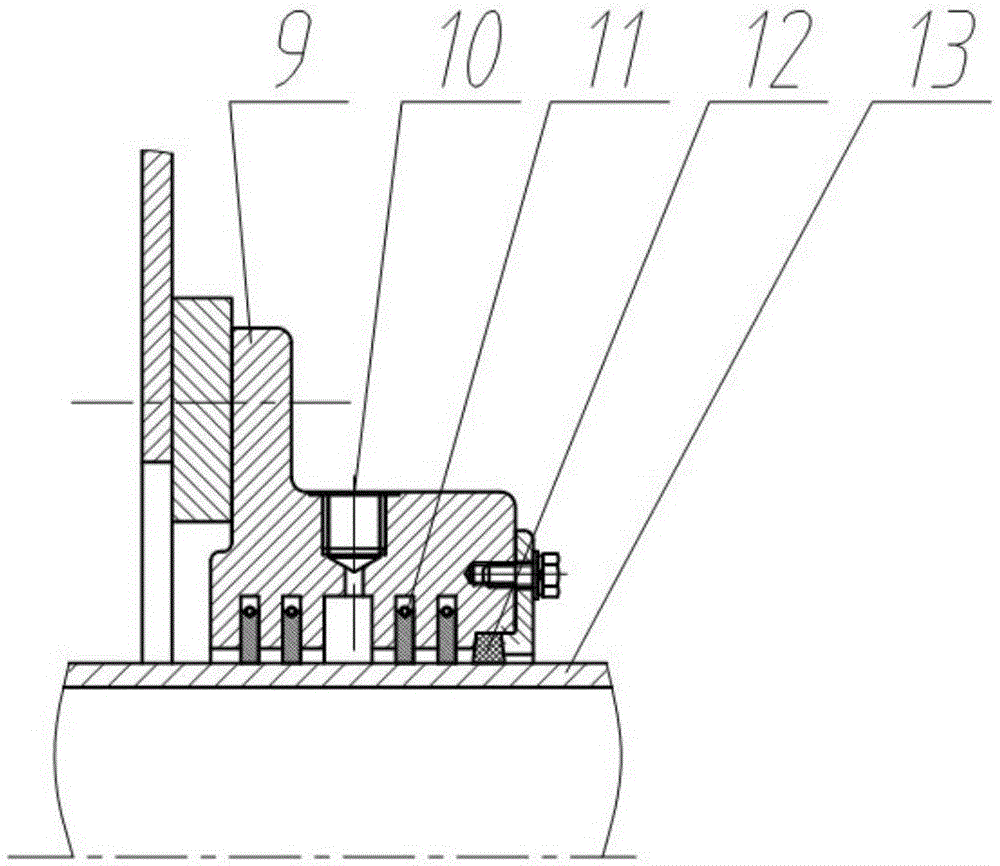
[0028] One embodiment of the present invention discloses a gas compressor, such as figure 1 Shown: including air inlet 1, casing 3, impeller 4, main shaft sealing device 6, main shaft 7 and bearing box 8; the front side of casing 3 is provided with a connecting flange surface, and air inlet 1 is fixed on the connecting flange by bolts On the surface, the impeller 4 is arranged in the casing 3, the main shaft 7 penetrates into the rear side of the impeller 4 in the casing 3, and the impeller 4 and the main shaft 7 can be connected by a flat key; the flat key connection can transmit torque and realize the radial direction of the impeller 4. At the same time, it is necessary to use the lock ...


PUM


Abstract

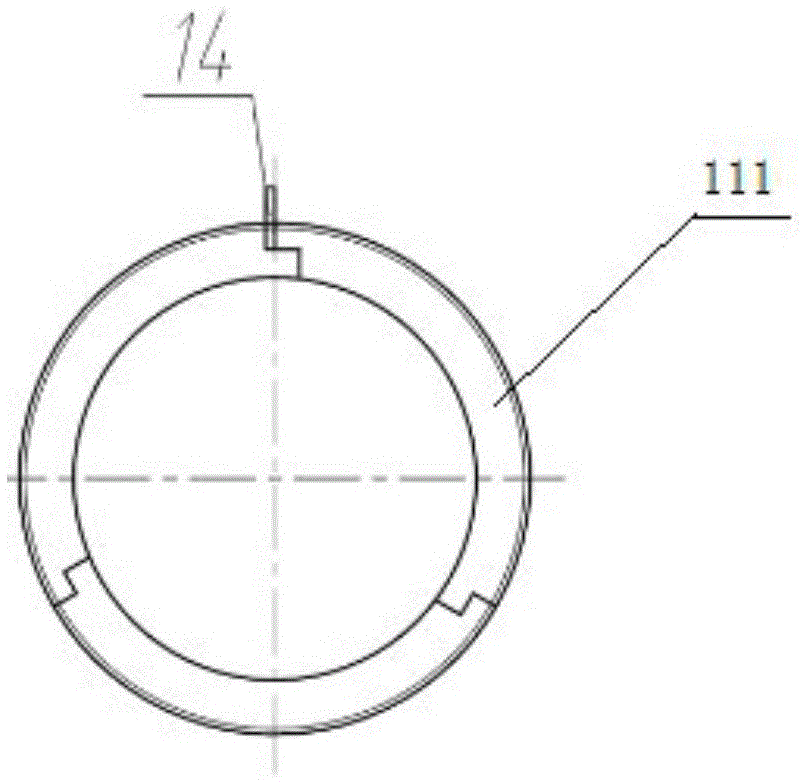
The invention provides a coal gas pressurizing machine which comprises an air inlet, a case, an impeller, a spindle sealing device, a spindle and a bearing box. A connecting flange face is arranged on the front side of the case, the air inlet is fixedly formed in the connecting flange face through a bolt, the spindle penetrates into the rear side of the case, and the spindle and the case are sealed through the spindle sealing device. The rear end of the spindle is fixed to the bearing box through a bearing. The spindle sealing device comprises a sealing body, a nitrogen sealing cavity, a plurality of carbon rings and a packing. The carbon rings are evenly arranged on the bottom side of the sealing body at intervals in a sleeving mode. The nitrogen sealing cavity is in a sealed cavity type, and is formed in the middle of the sealing body and located between the carbon rings. The packing is arranged on the outermost side of the spindle sealing device and connected with the sealing body. The coal gas pressurizing machine is reasonable in structure and excellent in whole machine sealing performance, meanwhile, large-flow flammable and combustible gas can be safely conveyed, it is effectively guaranteed that no coal gas is leaked, outside air is prevented from entering a fan, and the aims of poison prevention, explosion prevention and safe running are really achieved.

Description

technical field [0001] The invention relates to the technical field of fluid machinery, in particular to a gas compressor. Background technique [0002] The gas pressurization process is an important part of production and processing. In the occasions where a large amount of gas is used as a heat source, the gas compressor is the hub for mixing and pressurizing the gas to the user. For example, Chinese patent CN103899577A discloses a gas pressurized fan, which includes a fan casing, an air inlet, an impeller, a main shaft, a casing shaft seal, a bearing box and a base. It is characterized in that: the fan casing is made of welded steel plates, The front side of the fan casing is provided with a connecting flange surface, the air inlet is set on the connecting flange surface through bolts, the main shaft penetrates the rear side of the fan casing, and the main shaft and the fan casing are connected. The shaft seal of the casing is used for sealing, the rear end of the main s...

Claims


Application Information

Patent Timeline
IPC IPC(8): F04D17/10F04D29/10F04D29/12F04D29/28F04D29/66F04D29/16
CPCF04D17/10F04D29/104F04D29/122F04D29/162F04D29/284F04D29/662
Inventor 赵春成程宗祥黄蓉朱莉娅钱燕萍李玉香李明娟龚洋洁
Owner JIN TONG LING TECH GRP CO LTD
Learn More