Annular type combined password locking control valve

A combination of password and control valve technology, which is applied in the direction of valve details, valve devices, and devices to prevent accidental or unauthorized actions, can solve problems that plague enterprises such as energy-saving and efficient development, difficulty in adapting quickly and effectively, and increased production and operation costs. , to achieve the effect of solving economic losses and troubles, perfect functional design, and high security

Active Publication Date: 2016-05-25
黑龙江龙匠德工新能源科技有限公司
View PDF5 Cites 2 Cited by
  • Summary
  • Abstract
  • Description
  • Claims
  • Application Information

AI Technical Summary

Problems solved by technology

[0002] There are many types of locking valves used in today's market circulation, with single functions, and their management and anti-theft functions are based on zero. Operating costs increase year by year
[0003] However, the large and small valves and locking forms used in the transmission and distribution network systems of various industries are difficult to deal with difficult problems and energy-saving regulations such as water theft, heat theft, leakage, water and heat imbalance, and refusal to pay heat charges during production and operation. Management needs, from the locking control form, structure and material selection, there are great defects, useless and short-term repeated replacement, maintenance costs increase year by year, bringing overwhelming economic pressure to the economic management of enterprises
Long-term constraints have plagued the pace of energy-saving and efficient development of enterprises

Method used


Image

  • Annular type combined password locking control valve
  • Annular type combined password locking control valve
  • Annular type combined password locking control valve

Examples


Embodiment 1

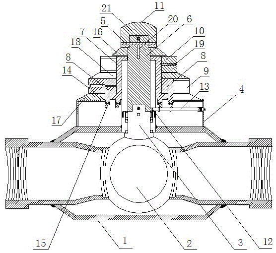
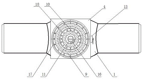
[0018] The ring-type combined password lock control valve of the present invention is composed of a valve housing 1, a valve core 2, a valve shaft 3 and a password lock mechanism, and a built-in lock fixing box 4 and a valve housing 1 are fixed directly above the valve housing 1. The valve shaft 3 connected to the top of the core 2 is placed in the built-in lock fixing box 4, and the bottom end of the diameter valve shaft 6 is placed in the built-in lock fixing box 4 and is fixedly connected with the top of the valve shaft 3 through a pin shaft. The middle and lower part of the diameter valve shaft 6 is sequentially set with the lock code ring I7 and the lock code ring II8 from the inside to the outside. The bottoms of the lock code ring I7 and the lock code ring II8 are placed in the built-in lock fixing box 4. Coded manual handle II9 is ​​set on the code lock ring II8, coded manual handle I10 is set on the lock code ring I7 above the coded manual handle II9, and the valve sha...

Embodiment 2

[0020] The ring-type combined password lock control valve of the present invention is composed of a valve housing 1, a valve core 2, a valve shaft 3 and a password lock mechanism, and a built-in lock fixing box 4 and a valve housing 1 are fixed directly above the valve housing 1. The valve shaft 3 connected to the top of the core 2 is placed in the built-in lock fixing box 4, and the bottom end of the diameter valve shaft 6 is placed in the built-in lock fixing box 4 and is fixedly connected with the top of the valve shaft 3 through a pin shaft. The middle and lower part of the diameter valve shaft 6 is sequentially set with the lock code ring I7 and the lock code ring II8 from the inside to the outside. The bottoms of the lock code ring I7 and the lock code ring II8 are placed in the built-in lock fixing box 4. Coded manual handle II9 is ​​set on the code lock ring II8, coded manual handle I10 is set on the lock code ring I7 above the coded manual handle II9, and the valve sha...

Embodiment 3

[0022] The ring-type combined password lock control valve of the present invention is composed of a valve housing 1, a valve core 2, a valve shaft 3 and a password lock mechanism, and a built-in lock fixing box 4 and a valve housing 1 are fixed directly above the valve housing 1. The valve shaft 3 connected to the top of the core 2 is placed in the built-in lock fixing box 4, and the bottom end of the diameter valve shaft 6 is placed in the built-in lock fixing box 4 and is fixedly connected with the top of the valve shaft 3 through a pin shaft. The middle and lower part of the diameter valve shaft 6 is sequentially set with the lock code ring I7 and the lock code ring II8 from the inside to the outside. The upper part of the code circle II8 is fixedly connected with the password manual handle II9, and the upper part of the code lock ring I7 above the password manual handle II9 is ​​set with the password manual handle I10, and the top of the diameter valve shaft 6 is installed ...


PUM


Abstract

The invention discloses an annular type combined password locking control valve, and relates to an efficient multifunctional valve integrating an oil supply system, a gas supply system, a heat supply system and a water supply system. The valve is composed of a valve shell, a valve element, a valve shaft and a password lock mechanism. A hidden lock fixing box is fixed over the valve shell, the valve shaft connected with the top end of the valve element is arranged in the hidden lock fixing box, the bottom end of a latus-rectum valve shaft is arranged in the hidden lock fixing box and fixedly connected with the top end of the valve shaft through a pin shaft. The password lock mechanism is sequentially sleeved with a lock password ring I and a lock password ring II from inside to outside from the lower middle part of the latus-rectum valve shaft. The bottom of the lock password ring I and the bottom of the lock password ring II are arranged in the hidden lock fixing box. The portion, above the hidden lock fixing box, of the upper portion of the lock password ring II is sleeved with a password manual rotary handle II, and the portion, above the password manual rotary handle II, of the upper portion of the lock password ring I is sleeved with a password manual rotary handle I. The top of the latus-rectum valve shaft is provided with a valve shaft locking cap. The annular type combined password locking control valve is reasonable in structural design and has quite strong control, management, thievery prevention and adjustment functions.

Description

technical field [0001] The invention relates to a four-in-one high-efficiency multi-functional valve for professional control, management, prevention and adjustment of oil and gas, heat supply and water supply systems, in particular to a ring-type combined code lock control valve. Background technique [0002] There are many types of locking valves used in today's market circulation, with single functions, and their management and anti-theft functions are based on zero. Operating costs increase year by year. [0003] However, the large and small valves and locking forms used in the transmission and distribution network systems of various industries are difficult to deal with difficult problems and energy-saving regulations such as water theft, heat theft, leakage, water and heat imbalance, and refusal to pay heat charges during production and operation. The demand for management, from the form of locking control, to the selection of structure and material, has great defects...

Claims


Application Information

Patent Timeline
Patent Type & Authority Applications(China)
IPC IPC(8): F16K35/08
CPCF16K35/08
Inventor 林维金
Owner 黑龙江龙匠德工新能源科技有限公司
Why Eureka
Try Eureka