
Vertical secondary combustion chamber structure for medical waste incineration system

A technology of medical waste and secondary combustion chamber, applied in incinerators, combustion methods, combustion types, etc., can solve the problems of ash formation, accumulation, and inability to clean ash in the secondary combustion chamber, and achieve improved refrigeration efficiency, convenient use, and simple structure Effect

Inactive Publication Date: 2016-05-25
江正云 +2
View PDF6 Cites 0 Cited by
  • Summary
  • Abstract
  • Description
  • Claims
  • Application Information

AI Technical Summary

Problems solved by technology

[0002] At present, in the treatment of medical waste, the incineration system is generally used. The secondary combustion chamber in the current incineration system is horizontal. After a long time of production operation, it is easy to cause serious ash accumulation in the secondary combustion chamber, and it cannot be cleaned, which cannot meet the requirements Continuous production, but the serious ash formation in the second combustion chamber is mainly due to the short residence time of the flue gas and insufficient combustion of waste, forming a large amount of soot, which will eventually accumulate on the flue wall and form ash formation over time

Method used


Image

  • Vertical secondary combustion chamber structure for medical waste incineration system

Examples


Embodiment Construction

[0014] The specific embodiments of the present invention will be further described below in conjunction with the accompanying drawings. It should be noted here that the descriptions of these embodiments are used to help understand the present invention, but are not intended to limit the present invention. In addition, the technical features involved in the various embodiments of the present invention described below may be combined with each other as long as they do not constitute a conflict with each other.

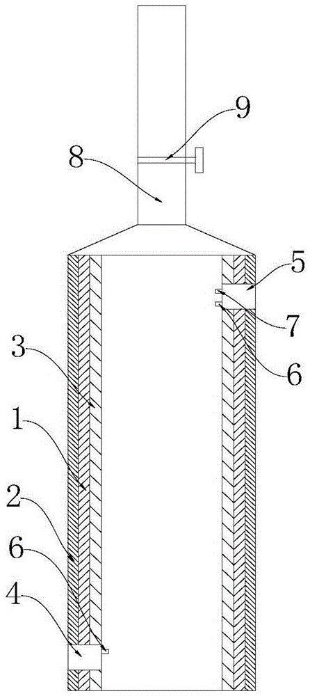
[0015] Such as figure 1 The vertical secondary combustion chamber structure shown in the medical waste incineration system includes a secondary combustion chamber body 1 with a flue, the secondary combustion chamber body 1 is a cylindrical structure, and the side wall of the secondary combustion chamber body 1 is opened The air outlet 4 and the air outlet 5, the air inlet 4 is located at the side wall of the second combustion chamber body 1 near the bottom, the air outl...


PUM


Abstract

The invention discloses a vertical secondary combustion chamber structure for a medical waste incineration system. The vertical secondary combustion chamber structure comprises a secondary combustion chamber body provided with a flue, wherein the secondary combustion chamber body is of a columnar structure, an air inlet and an air outlet are formed in the side wall of the secondary combustion chamber body, the air inlet is formed in the position, close to the bottom end, of the side wall of the secondary combustion chamber body, and the air outlet is formed in the position, close to the top end, of the side wall of the secondary combustion chamber body; two temperature sensors and an oxygen sensor are arranged on the inner wall of the secondary combustion chamber body, the two temperature sensors are arranged at the positions of the air inlet and the air outlet respectively, and the oxygen sensor is arranged at the position of the air outlet. By constructing the secondary combustion chamber body into the vertical columnar structure and arranging the temperature sensors at the positions of the air inlet and the air outlet, the temperature of smoke entering the secondary combustion chamber body and the temperature of smoke at the outlet are detected in real time; meanwhile, the oxygen sensor is arranged at the position of the outlet to detect the oxygen content of smoke at the outlet, the volume of air blown into the secondary combustion chamber body and the amount of auxiliary fuel can be adjusted in time, smoke can burn sufficiently, and ash forming on the inner wall of the secondary combustion chamber body is effectively reduced.

Description

technical field [0001] The invention relates to the technical field of medical waste incineration, in particular to a vertical secondary combustion chamber structure used in a medical waste incineration system. Background technique [0002] At present, in the treatment of medical waste, the incineration system is generally used. The secondary combustion chamber in the current incineration system is horizontal. After a long time of production operation, it is easy to cause serious ash accumulation in the secondary combustion chamber, and it cannot be cleaned, which cannot meet the requirements Continuous production, but the serious ash formation in the secondary combustion chamber is mainly due to the short residence time of flue gas and insufficient combustion of waste, forming a large amount of soot, which eventually accumulates on the flue wall, and ash formation will form over time. [0003] Therefore, it is necessary to design a novel secondary combustion chamber structu...

Claims


Application Information

Patent Timeline
Patent Type & Authority Applications(China)
IPC IPC(8): F23G7/00F23G5/16F23G5/50
CPCF23G7/00F23G5/16F23G5/50F23G2207/101
Inventor 江正云杨巍李建康
Owner 江正云
Learn More