Substrate cleaning method

A technology for substrates and cleaning water, applied in cleaning methods and utensils, cleaning methods using liquids, chemical instruments and methods, etc., can solve problems such as poor cleaning, slow delivery of substrates 100, large drying capacity, etc., to avoid strips Effects of mura, accelerated cleaning speed, and improved transport speed

Active Publication Date: 2016-05-25
WUHAN CHINA STAR OPTOELECTRONICS TECH CO LTD
View PDF5 Cites 18 Cited by
  • Summary
  • Abstract
  • Description
  • Claims
  • Application Information

AI Technical Summary

Problems solved by technology

[0006] At present, the cleaning process of glass substrates usually involves the process of cleaning with aqueous solution and the process of drying the glass substrate with a drying device after cleaning with aqueous solution, such as figure 1 As shown, it is an existing method for cleaning a substrate. Firstly, an aqueous solution is used to clean the pollutants on the substrate 100, and secondly, a drying device is used to dry the remaining cleaning water on the substrate 100. The drying device includes cleaning the substrate 100. A conveying mechanism (not shown) for conveying, and an air knife device 300 for drying residual cleaning water on the substrate 100, the air knife device 300 includes several air knives 350 arranged in the horizontal direction, during the drying process Among them, since the substrate 100 is placed horizontally, a large amount of residual cleaning water on the substrate 100 will be concentrated in the center of the substrate 100, resulting in a huge amount of drying. It tends to form a meniscus-shaped water block attached to the surface of the substrate 100, and the two sides of the water block are easy to flow back to form water spots on the surface of the substrate 100, resulting in poor cleaning, resulting in stripes on the liquid crystal display panel in the subsequent process. Mura (uneven color display) and other adverse phenomena; in addition, in the existing drying device, the substrate 100 is transported at a slow speed, resulting in cleaning quality and efficiency that cannot meet the current demand for high production capacity

Method used


Image

  • Substrate cleaning method
  • Substrate cleaning method
  • Substrate cleaning method

Examples


Embodiment Construction

[0042] In order to further illustrate the technical means adopted by the present invention and its effects, the following describes in detail in conjunction with preferred embodiments of the present invention and accompanying drawings.

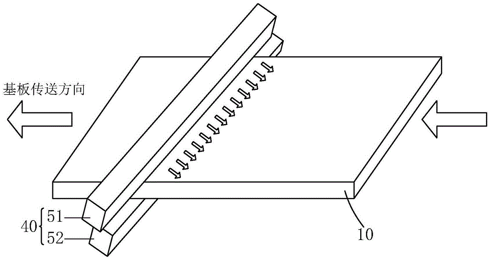
[0043] see Figure 2-4 , the present invention provides a substrate cleaning method, comprising the following steps:

[0044] Step 1. Provide a substrate 10 , and clean the substrate 10 with an aqueous solution to remove pollutants on the substrate 10 .

[0045] Specifically, the substrate 10 may be a TFT substrate, an unfinished TFT substrate, or a plain glass substrate.

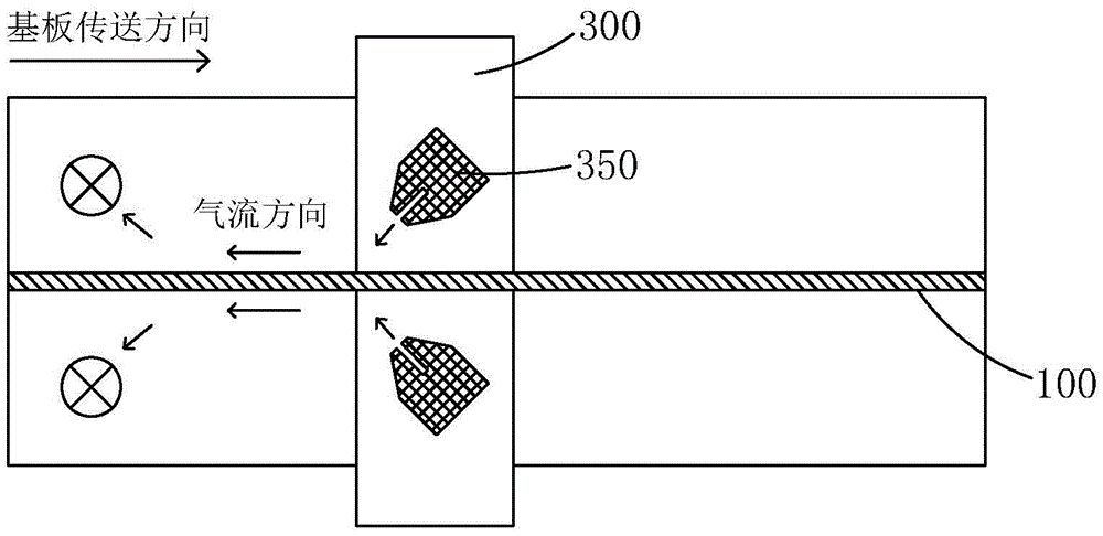
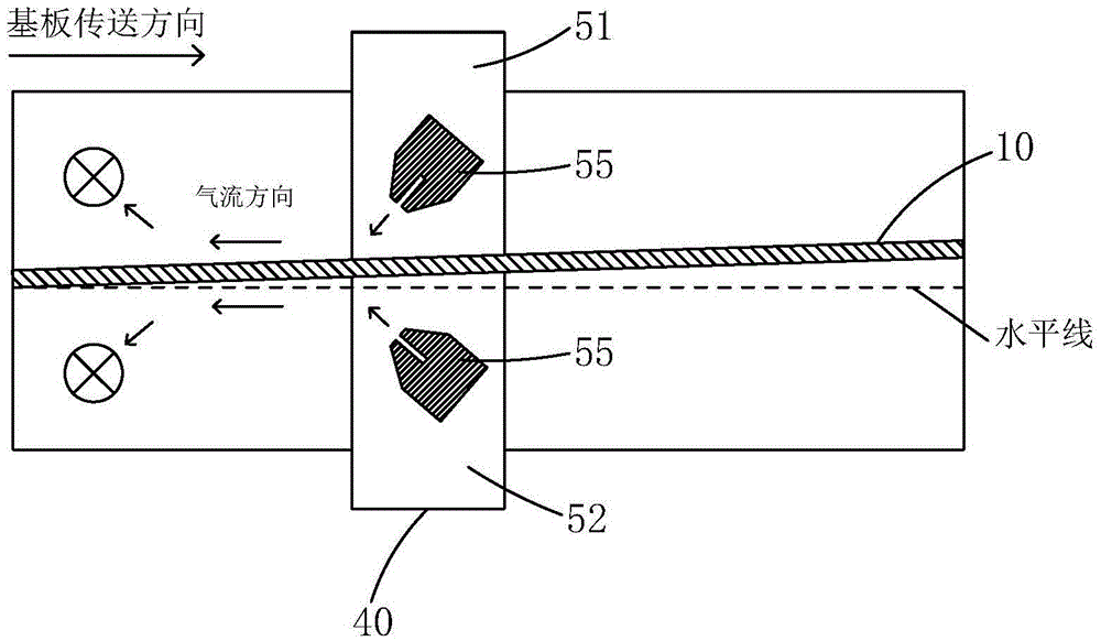
[0046] Step 2, providing a first drying device, the first drying device includes a transfer wheel (not shown) for transferring the substrate 10, and a traditional air knife device 40 for removing residual cleaning water on the substrate 10, the The traditional air knife device 40 includes a first air knife unit 51 corresponding to the top of the substrate 10 and a second ...


PUM


Abstract

The invention provides a substrate cleaning method. A substrate (10) is arranged to be at different inclination angles and in different inclination modes in the drying process, and a traditional air knife device (40) is adopted for thoroughly removing cleaning water remaining on the substrate (10). Or, a frequency-adjustable air knife device (70) is adopted as an air knife device for a first blow-drying procedure in the drying process, the traditional air knife device (40) is adopted as an air knife device for a second blow-drying procedure in the drying process, and the cleaning water remaining on the substrate (10) is thoroughly removed in the two blow-drying procedures; meanwhile, the substrate (10) can be further arranged to be at different inclination angles and in different inclination modes to prevent the cleaning water from flowing back, increase the drying speed and avoid that strip-shaped mura is generated in subsequent procedures. In addition, the substrate (10) conveying speed can be properly increased thanks to the high drying speed of the frequency-adjustable air knife device (70), so that the substrate (10) cleaning speed is increased.

Description

technical field [0001] The invention relates to the field of display technology, in particular to a substrate cleaning method. Background technique [0002] With the development of display technology, liquid crystal displays (Liquid Crystal Display, LCD) and other flat display devices are widely used in mobile phones, TVs, personal digital assistants due to their advantages of high image quality, power saving, thin body and wide application range. , digital cameras, notebook computers, desktop computers and other consumer electronics products have become the mainstream of display devices. [0003] Most of the liquid crystal display devices currently on the market are backlight liquid crystal displays, which include a liquid crystal display panel and a backlight module. The working principle of the liquid crystal display panel is to place liquid crystal molecules between two parallel glass substrates. There are many vertical and horizontal small wires between the two glass s...

Claims


Application Information

Patent Timeline
Patent Type & Authority Applications(China)
IPC IPC(8): F26B21/00B08B3/00
CPCB08B3/00F26B21/004
Inventor 郑俊丰
Owner WUHAN CHINA STAR OPTOELECTRONICS TECH CO LTD
Why Eureka
Try Eureka