Indicating method and system for scanning area

A scanning area and indication technology, applied in computerized tomography scanners, echo tomography, etc., can solve the problems of not being very conspicuous, reducing the use efficiency of CT machines, and long positioning process, so as to improve flexibility, improve use efficiency, The effect of shortening the time

Inactive Publication Date: 2016-06-01
SIEMENS SHANGHAI MEDICAL EQUIP LTD
View PDF5 Cites 7 Cited by
  • Summary
  • Abstract
  • Description
  • Claims
  • Application Information

AI Technical Summary

Problems solved by technology

In the current CT machine, the preliminary positioning is mainly realized by irradiating the pre-scan section position of the examinee with the laser pointer installed on the frame, but this method requires the operator to manually operate the bed shifting button to move the bed board to the position of the examinee. The positioning can only be realized in the scanning hole of the rack, and the light emitted by the laser transmitter is thin and not very conspicuous, which makes the positioning process longer and reduces the efficiency of the CT machine

Method used


Image

  • Indicating method and system for scanning area
  • Indicating method and system for scanning area
  • Indicating method and system for scanning area

Examples


Embodiment Construction

[0028] In order to make the purpose, technical solution and advantages of the present invention clearer, the following examples are given to further describe the present invention in detail.

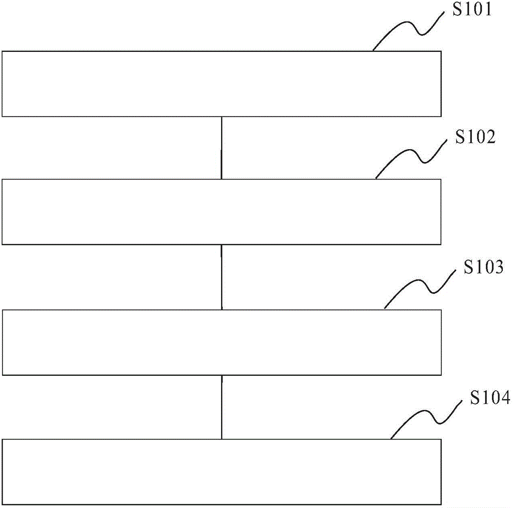
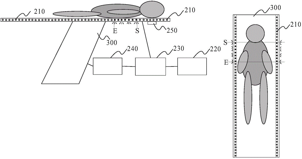
[0029] figure 1 It is an exemplary flow chart of a method for indicating a scanning area in an embodiment of the present invention. In the embodiment of the present invention, an LED light group composed of a plurality of LED indicator lights can be provided on any side of the examination bed board, or an LED lamp group composed of a plurality of LED indicators can be provided on the two sides of the examination bed board respectively. An LED light group composed of indicator lights, the LED light group is arranged along the direction of entry and exit of the examination bed board, and each LED indicator light in the LED light group is established with a corresponding position on the examination bed board Corresponding relationship. For example, LED indicator lights can be inlaid on the ...


PUM


Abstract

The invention discloses an indicating method and system for a scanning area. The method comprises steps as follows: according to a predetermined scanning mode of a current patient, the scanning area corresponding to the patient is estimated, and a table board position corresponding to the scanning area is determined; the scanning area comprises a scanning starting position; according to the correspondence between the table board position and LED indicating lamps arranged on at least one side of a table board, the LED indicating lamps corresponding to the scanning area are controlled to be lit in the set manner; an indicating interval of the lit LED indicating lamps is used for indicating the position, located on the table board, of a to-be-scanned part of the current patient; when the position, located on the table board, of the to-be-scanned part of the current patient is determined to be consistent with the indicating interval of the lit LED indicating lamps, the table board position, corresponding to the scanning starting position, of the table board of a examining table is controlled to move to an exposure starting position of a CT (computed tomography) machine. According to the technical scheme, the use efficiency of the CT machine can be improved.

Description

technical field [0001] The invention relates to the field of medical equipment, in particular to a scanning area indication method and system. Background technique [0002] In the application of medical equipment, such as X-ray computer tomography (Computed Tomography, CT) scanning, the patient needs to be placed on the appropriate position of the examination bed, and the patient can be placed horizontally into the scanning area by moving the bed. Scan check. When scanning and checking, it usually includes two stages. The first stage is the stage of positioning scanning (toposcan), that is, the stage of determining the scanning range, which is used to determine the start position, end position and position of the rack (gantry). slope. The second stage is the tomoscan stage, which is the real scanning imaging stage. [0003] Wherein, in order to realize the positioning scan in the first stage, it is also necessary to perform a preliminary positioning on the scan area of ​​...

Claims


Application Information

Patent Timeline
Patent Type & Authority Applications(China)
IPC IPC(8): A61B6/03
Inventor 虞可杰
Owner SIEMENS SHANGHAI MEDICAL EQUIP LTD
Why Eureka
Try Eureka