Spouted circulating fluidized bed

A circulating fluidized bed and spouted fluidized bed technology, applied in chemical/physical processes, chemical instruments and methods, etc., can solve the problems of easy occurrence of short circuits and channeling, large back mixing, and lowering the yield of target products, etc. Achieve the effect of eliminating and easy-bonding particle agglomeration, avoiding delamination or junction

Inactive Publication Date: 2016-06-01
SHAANXI YUHANG ELECTRONICS
View PDF0 Cites 0 Cited by
  • Summary
  • Abstract
  • Description
  • Claims
  • Application Information

AI Technical Summary

Problems solved by technology

The disadvantage of this fluidized bed reactor is that the gas is only distributed once, the gas distribution is uneven, and it is easy to generate large bubbles, large back-mixing, short circuit and channeling, which affect the effective contact time between the gas and the catalyst. and contact area, reducing the reaction efficiency
The depth of reaction cannot be flexibly controlled, and it is easy to cause the secondary reaction of the target product, thus reducing the yield of the target product

Method used


Image

  • Spouted circulating fluidized bed

Examples


Embodiment Construction

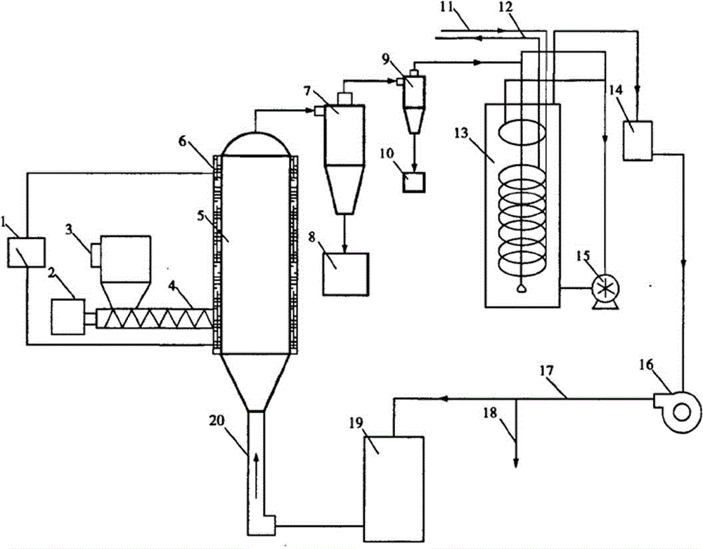
[0018] A spouted circulating fluidized bed is composed of a monitoring system 1, a feed system, a main reactor, a gas-solid separation system, a filter 14, a gas purification system, a gas recovery system, and a preheating system 20 connected end to end in sequence. The main reactor is the spouted fluidized bed reactor 5. The feeding system is a vibrating feeder 3, and is connected with a spouted fluidized bed reactor 5 through a screw 4. The spouted fluidized bed reactor 5 is covered with a layer of heater 6 . The gas-solid separation system is divided into two-stage separation devices connected in sequence, namely the first-stage cyclone separator 7 and the first-stage cyclone separator 9 . The bottom of the primary cyclone separator 7 is connected to the primary carbon collection box 8 , and the bottom of the secondary cyclone separator 9 is connected to the secondary carbon collection box 10 . The condensing system is a bubbling secondary spray condenser 13, and is provi...


PUM


Abstract

The present invention relates to the field of chemical industry equipment, particularly to a spouted circulating fluidized bed reactor, wherein the spouted circulating fluidized bed comprises a monitoring system, a material feeding system, a main reactor, a gas-solid separation system, a filter, a gas purification system, a gas recovery system and a pre-heating system, and the monitoring system, the material feeding system, the main reactor, the gas-solid separation system, the filter, the gas purification system, the gas recovery system and the pre-heating system are sequentially connected in a head-tail-connection manner. According to the present invention, with the spouted circulating fluidized bed, the disadvantages that the contact of the gas phase and the solid phase in the ring-gap region is poor and the spouting under the high bed layer is instable are overcome, the phenomenon that layering or section communication is easily generated inside the fluidized bed is avoided, the generation of the dead region on the bottom portion of the ring-gap region and the agglomeration of the easily bonded particles are basically eliminated, the non-condensable gas is adopted as the circulating fluidized bed so as to avoid the use of the expensive external inert gas, and the advantages of easy industrialized scale-up and low operating cost are provided.

Description

technical field [0001] The invention relates to the field of chemical equipment, in particular to a spray circulating fluidized bed reactor. Background technique [0002] The fluidized bed reactor is mainly used in the aromatization reaction. The traditional fluidized bed reactor includes the tower body, the gas inlet and outlet ports at the top and bottom of the tower body, and a gas distributor is set at the gas inlet at the bottom end. Inject into the reactor near the outlet position, mix evenly with the gas coming in from the sparger, and move upwards driven by the gas velocity. At the upper part of the reactor, the catalyst is separated from the gas under the action of gravity, and is exported out of the reactor through the outlet pipe. The disadvantage of this kind of fluidized bed reactor is that the gas is only distributed once, the gas distribution is uneven, and it is easy to generate large bubbles, large back-mixing, short circuit and channeling, which affect the ...

Claims


Application Information

Patent Timeline
Patent Type & Authority Applications(China)
IPC IPC(8): B01J8/24
Inventor 郝青
Owner SHAANXI YUHANG ELECTRONICS
Why Eureka
Try Eureka