
Soil screening machine

A screening machine and soil technology, applied in screening, solid separation, chemical instruments and methods, etc., can solve the problem that manual screening cannot meet the requirements of the development of the times, and achieve the effect of reducing the intensity of screening work, reducing costs, and facilitating screening.

Inactive Publication Date: 2016-06-01
SHENGZHOU YIHAI MOTOR PARTS FACTORY
View PDF0 Cites 6 Cited by
  • Summary
  • Abstract
  • Description
  • Claims
  • Application Information

AI Technical Summary

Problems solved by technology

[0002] As the pace of development in our country is accelerating year by year, and the strength of science and technology is constantly strengthening, my country's industry and agriculture will surely develop in the direction of mechanization, automation, and modernization, which brings an extremely broad development space for soil screening machines. According to market orientation , consumer needs, and the development direction of science and technology. Various data show that in industrial and agricultural production, traditional human screening can no longer meet the requirements of the development of the times. From the perspective of saving labor costs and time costs, soil screening machines are cost-saving. Therefore, in order to save labor costs and time costs, improve screening efficiency, and reduce screening workload, research, design and manufacture of soil screening machines have become a very important topic.

Method used


Image

  • Soil screening machine
  • Soil screening machine
  • Soil screening machine

Examples


Embodiment Construction

[0017] The preferred embodiments of the present invention will be described in further detail in conjunction with the accompanying drawings.

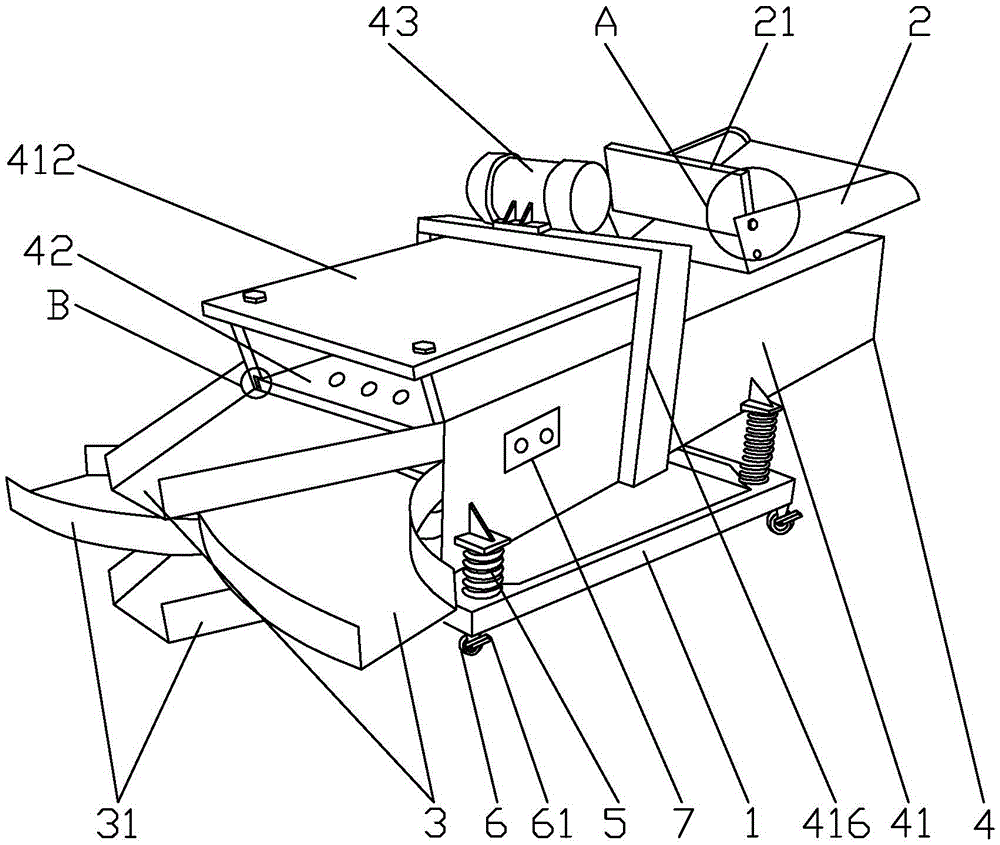
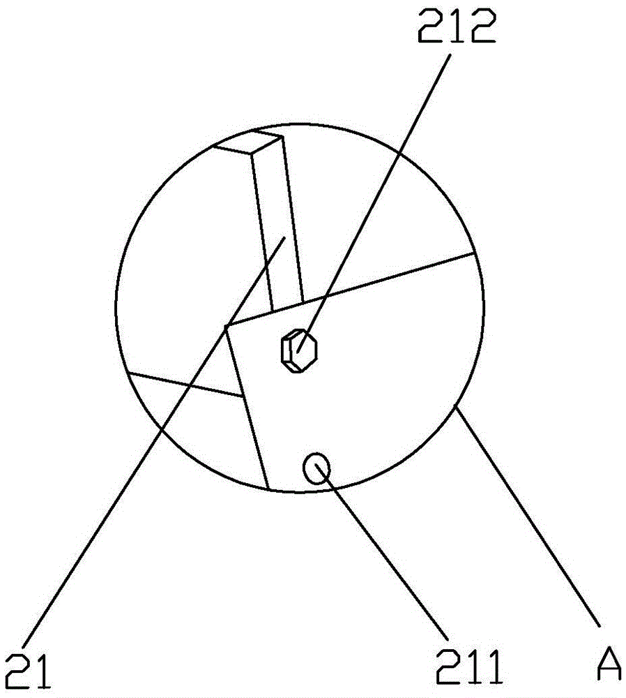
[0018] like Figure 1-4 Shown, a kind of soil screening machine comprises base frame 1, feed port 2, discharge port 3 and screening device 4, and described screening device 4 is installed on the bottom frame 1 top, and described feed port 2 is installed on the screening device 4. On the upper side of the head, the outlet 3 is installed at the tail of the screening device 4, the inlet 2 is provided with an adjustment board 21, and both sides of the adjustment board 21 are provided with a jack 211 , both sides of the feed port 2 are provided with at least two sockets 211, the feed port 2 and the adjusting plate 21 are connected together in the socket 211 by screwing the bolts 212, and the bolts 212 are inserted into the sockets 211. In the different jacks 211 of the feed port 2, the size of the feed port 2 can be adjusted to control the ...


PUM


Abstract

The invention mainly discloses a soil screening machine. According to the technical scheme, the soil screening machine comprises a bottom frame, a feeding port, discharging ports and a screening device. An adjusting inserting plate is arranged at the position of the feeding port. Springs are arranged on the bottom frame. The springs are connected with the screening device. A supporting frame is arranged on the two outer sides of a vibrating frame. A vibration motor is installed on the supporting frame. The two inner sides of the vibrating frame are each provided with at least two first sliding grooves. Vibrating screens are connected into the first sliding grooves in a sliding manner. The hole diameters of screen holes of the vibrating screens on different layers are sequentially reduced from top to bottom. The upper side of the vibrating frame is provided with a dustproof cover. A second sliding groove is formed in the bottom of the dustproof cover. The second sliding groove is provided with a rake connected with the second sliding groove in a sliding manner. An air cylinder is further arranged at the bottom of the dustproof cover. Baffles are arranged on the two sides of the discharging ports. The widths of the discharging ports are gradually reduced from the head portion to the tail portion, and the discharging directions of the discharging ports are different. The soil screening machine has the beneficial effects of being simple in structure, high in screening efficiency, convenient to use and capable of saving cost.

Description

technical field [0001] The invention relates to the field of agricultural machinery and equipment, in particular to a soil screening machine. Background technique [0002] As the pace of development in our country is accelerating year by year, and the strength of science and technology is constantly strengthening, my country's industry and agriculture will surely develop in the direction of mechanization, automation, and modernization, which brings an extremely broad development space for soil screening machines. According to market orientation , consumer needs, and the development direction of science and technology. Various data show that in industrial and agricultural production, traditional human screening can no longer meet the requirements of the development of the times. From the perspective of saving labor costs and time costs, soil screening machines are cost-saving. Therefore, in order to save labor costs and time costs, improve screening efficiency, and reduce scree...

Claims


Application Information

Patent Timeline
Patent Type & Authority Applications(China)
IPC IPC(8): B07B1/28B07B1/42B07B1/46B03C1/02
CPCB03C1/02B07B1/28B07B1/42B07B1/46B07B13/16
Inventor 陈意
Owner SHENGZHOU YIHAI MOTOR PARTS FACTORY
Learn More