Movable sand blowing polishing machine achievement method

A realization method, polishing machine technology, applied in grinding/polishing equipment, non-mechanical abrasive jet generation equipment, explosion generation devices, etc., can solve the problems of easy blocking of sandblasting pipes, etc., to reduce wear, The effect of reducing work intensity and increasing effective power

Inactive Publication Date: 2016-06-01
王丰利
View PDF0 Cites 2 Cited by
  • Summary
  • Abstract
  • Description
  • Claims
  • Application Information

AI Technical Summary

Problems solved by technology

[0003] The invention solves the problem that the traditional abrasives easily block the sandblasting pipe by setting a mobil

Method used


Image

  • Movable sand blowing polishing machine achievement method

Examples


Embodiment 1

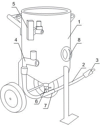
[0019] like figure 1 As shown, this embodiment includes a box body 1, a sandblasting pipe 2 and a nozzle 3, the box body 1 is provided with an air intake control valve 4 and an exhaust control valve 5, and the sand outlet at the bottom of the box body 1 is installed with a Butterfly sand control valve 6, one end of sandblasting pipe 2 is connected to box body 1 through air intake control valve 4, and the other end is connected to butterfly sand control valve 6 and nozzle 3 respectively through thickened sand outlet tee 7, and also includes The two casters and the supporting feet arranged on the bottom of the box body 1 are distributed in a triangular shape. According to the stability of the triangle, the combination of casters and feet can provide stable support and fixation during the polishing process; when moving, just tilt one end of the cabinet 1 and push the cabinet 1, and the casters can roll Quickly move the sandblasting machine, reducing the work intensity of workers...

Embodiment 2

[0022] like figure 1 As shown, on the basis of Embodiment 1, this embodiment also includes an observation port 8 arranged in the middle of the box body 1 , and tempered glass is installed on the observation port 8 . An observation port 8 is set in the middle and lower part of the box body 1, which can be used by the operator to check the remaining amount of abrasive at any time, which is convenient for adding abrasive in time to ensure sandblasting efficiency; the installation of high-strength tempered glass can avoid abrasive Continuous impact on the observation port 8 will cause the glass to break.


PUM


Abstract

The present invention discloses a movable sand blowing polishing machine achievement method. The movable sand blowing polishing machine comprises a box, a sand blasting pipe and a blasting nozzle, wherein the box is provided with a gas inlet control valve and a gas discharge control valve, the sand outlet position on the bottom portion of the box is provided with a butterfly sand adjustment valve, one end of the sand blasting pipe is connected to the box through the gas inlet control valve, the other end is respectively connected to the butterfly sand adjustment valve and the blasting nozzle through a thickened sand outlet three-way valve, the movable sand blowing polishing machine further comprises two foot wheels and a support foot, the foot wheels and the support foot are arranged on the bottom portion of the box and are distributed in a triangular manner, the thickened sand outlet three-way valve and the butterfly sand adjustment valve are independently arranged, the thickened sand outlet three-way valve is improved to increase the bottom portion wall thickness so as to increase the wear time, and the 90 DEG vertical sand falling port inside the three-way valve is changed into the 45 DEG inclined sand falling port so as to form the co-directional gas flow path with the gas flow from the back, such that the effective power of the sand inside the sand valve is increased, the bounce and the convolution of the abrasive material on the bottom portion of the sand valve are reduced, the wear on the sand outlet three-way valve and the sand blasting pipe is reduced, and the equipment use rate is enhanced.

Description

technical field [0001] The invention relates to the field of mechanical production, in particular to a method for realizing a mobile sand blasting and polishing machine. Background technique [0002] The structural principle of the sandblasting machine is to use compressed air to transport sand powder particles from the sand storage tank of the equipment to the surface of the object to be sandblasted and polished. This process is called sandblasting, and its main function is to improve the surface of the object. rough state. The key points to determine the sandblasting effect of the sandblasting machine are: suitable sand flow and suitable compressed air flow. The size of the compressed air determines that the flow velocity in the pipe should be greater than the settling velocity of the maximum abrasive flow process of the sandblasting machine. The aerodynamic force is sufficient to control the friction loss and the sum of the resistance of the abrasive in the pipeline, whi...

Claims


Application Information

Patent Timeline
IPC IPC(8): B24C5/08B24C5/00
CPCY02P70/10
Inventor 王丰利
Owner 王丰利
Why Eureka
Try Eureka