Reinforcing steel bar fixing device

A technology of fixers and steel bars, applied in the direction of structural elements, building components, building reinforcements, etc., can solve the problems of easy adsorption of water vapor, loss of strength, and inability to guarantee the probability of accidents

Inactive Publication Date: 2016-06-01
TAIWAN SUBTEL TECH CO
View PDF9 Cites 2 Cited by
  • Summary
  • Abstract
  • Description
  • Claims
  • Application Information

AI Technical Summary

Problems solved by technology

[0003] In the above-mentioned prior art, the blocks are generally common stones or bricks. In actual use, in order to pick out blocks of appropriate size and height, they are clamped with iron wires or straddled on the steel bars. This method props the steel bars to a certain height from the ground or formwork, or sets them at a certain distance between the steel bars, but it can only be applied to the structural surface of single-layer or multi-layer horizontal steel bars. For the steel bars with slopes such as stairs and ramps It is not easy to fix the structure. If the above stones or bricks are not only difficult to weave the reinforcement surface, but also will not be firm and slip during the grouting process.
Therefore, although this construction method has been quite convenient for a long time, it will inevitably suffer from huge weight before the cement grouting is completed, and it often collapses due to the displacement of the center of gravity or lateral force. The resulting momentary force is extremely high, and the stone or brick loses the strength to support the steel bar due to the breakage or fall off of the bound iron wire, causing the steel bar to collapse or collapse on the formwork, causing the concrete structure to be damaged and lose its expected strength. , so this method cannot guarantee reliable positioning without deviation in construction quality
[0004] In addition, if steel bars are assembled by welding, splicing, and tying, the force for lateral support is weak, and it is easy to collapse due to the shift of the center of gravity or the instability of the lateral force, and the probability of accidents due to human negligence cannot be guaranteed.
[0005] In fact, when the cement grouting operation is completed, it is in the state of sealing and filling. The prepared steel bars are mixed with the cement concrete. It is found that the steel bars are prone to moisture, corrosion and peeling around the steel bars of stones or bricks. The reason is the grouting. After that, the gap between the contact surface with the stone makes the water vapor easy to absorb and cause corrosion. Therefore, it cannot resist the long-term thermal expansion and contraction and the erosion of water vapor, resulting in the loss of strength of the structural surface of the coated steel bar and the inability to bear the structural weight pressure, resulting in future corrosion. greater potential crisis

Method used


Image

  • Reinforcing steel bar fixing device
  • Reinforcing steel bar fixing device
  • Reinforcing steel bar fixing device

Examples


Embodiment Construction

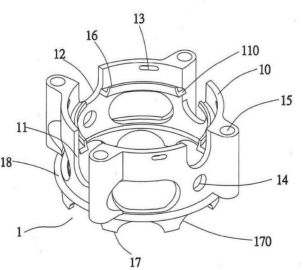
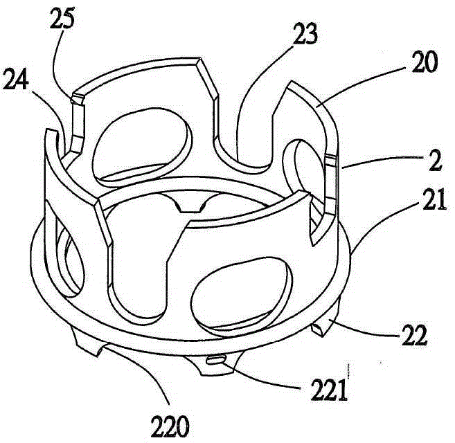
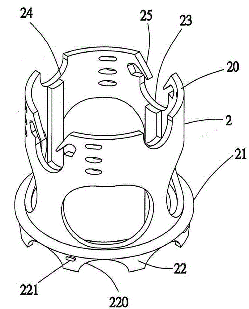
[0043] see Figure 1 to Figure 2C As shown, it is a schematic diagram of the structure of the base and the extension base of the steel bar fixer. The present invention can be combined and changed according to the requirements of single-layer or multi-layer steel bars. For the purpose of offset, moisture resistance and corrosion resistance, it mainly uses a light-weight and multi-functional base 1 as the basis to implement reinforcement weaving, and it can be combined with a group of extended bases 2 to form multi-layer reinforcement weaving according to height requirements. The content is detailed as follows:

[0044]The base 1 is a hollow cylinder with a porous surface, and the upper part is an upper bearing end 10. The upper bearing end 10 is respectively provided with a pair of deep grooves 11 and a pair of shallow grooves 12 in the axial direction on the end edge. The width of the deep groove 11 and the pair of shallow grooves 12 is at least the size of a steel bar diamet...


PUM


Abstract

The invention provides a reinforcing steel bar fixing device. The reinforcing steel bar fixing device can act on a plane and a slope according to the combined change of a single layer or multiple layers of reinforcing steel bars, the reinforcing steel bars cannot deflect in the cement grouting process, dampness can be prevented, and rusting of the reinforcing steel bars can be eradicated. The reinforcing steel bar fixing device mainly comprises a base which is a hollow cylinder with a porous face; the two ends of the base are bearing ends; a pair of deep trench grooves and a pair of shallow trench grooves are formed in the end edge of the upper bearing end in the axial direction; the reinforcing steel bars on the first layer are embedded in the grooves; the circumferential wall face of the base is provided with four hole trenches and one or more pairs of insertion hole seats; an inner ring trench groove is formed in the inner circumferential face of the base; a dampproof protruding ring is arranged on the circumferential wall face of the lower bearing end of the base; the upper bearing end is sleeved with and clamped to a set of extending bases at different heights; and the reinforcing steel bars on the second layer are arranged according to the required height. In addition, an M-shaped steel frame is arranged on any two insertion hole seats in the base in a striding manner, so that the purpose of rapid arrangement of the reinforcing steel bars is achieved.

Description

technical field [0001] The present invention relates to a support device for steel bars, especially a steel bar fixer that provides stability, support, partition, etc. and can be freely changed and combined according to actual conditions. Background technique [0002] At present, steel reinforcement structures are often used in construction projects, such as concrete roads, retaining walls, floor panels, foundations (pings), continuous walls, etc. Set up a single-layer or double-layer steel structure surface, and maintain each steel bar at a predetermined height with more than one block, so that the steel bar can be covered after cement grouting to form a steel bar-strengthened structural surface. [0003] In the above-mentioned prior art, the blocks are generally common stones or bricks. In actual use, in order to pick out blocks of appropriate size and height, they are clamped with iron wires or straddled on the steel bars. This method props the steel bars to a certain he...

Claims


Application Information

Patent Timeline
IPC IPC(8): E04C5/16
Inventor 张明辉
Owner TAIWAN SUBTEL TECH CO
Why Eureka
Try Eureka