Oil duct of novel camshaft phase regulator

A phase adjuster and camshaft technology, applied in the direction of machines/engines, engine components, mechanical equipment, etc., can solve the problems of high manufacturing cost, rotor holes, low processing efficiency, etc., achieve good consistency, improve work efficiency, reduce The effect of manufacturing costs

Inactive Publication Date: 2016-06-01
JIANGSU HAILONG ELECTRICAL APPLIANCE
View PDF0 Cites 2 Cited by
  • Summary
  • Abstract
  • Description
  • Claims
  • Application Information

AI Technical Summary

Problems solved by technology

Due to the need for machining, this design has high manufacturing cost and low processing efficiency because there are many holes on the rotor

Method used


Image

  • Oil duct of novel camshaft phase regulator
  • Oil duct of novel camshaft phase regulator

Examples


Embodiment 1

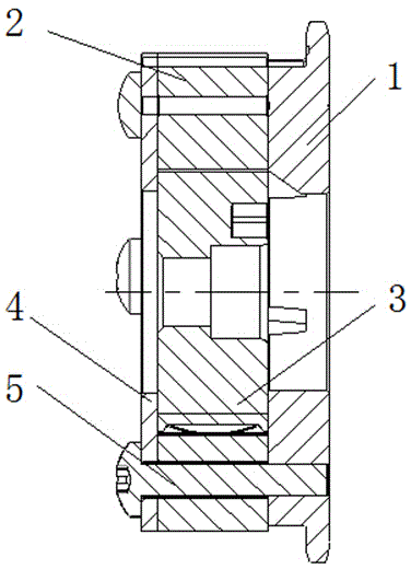
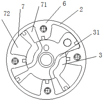
[0017] Such as figure 1 and figure 2 As shown, a novel camshaft phase adjuster oil channel of the present invention includes a sprocket 1, a stator 2, a rotor 3 and a rear cover 4, the rear end of the sprocket 1 is connected with the stator 2, and the rear end of the stator 2 is connected with the rear cover 4. The cavity formed by the sprocket 1, the stator 2 and the rear cover 4 is provided with a rotor 3, and the rear cover 4, the stator 2 and the sprocket 1 are fixed by screws 5, and the inner periphery of the stator 2 is provided with a screw 5 to pass through. The special-shaped end 6 of the special-shaped end 6 forms a special-shaped cavity 7 between two adjacent special-shaped ends 6. The outer periphery of the rotor 3 is provided with a special-shaped claw 8 that is placed in the special-shaped cavity 7 and fits the inner wall of the special-shaped cavity 7. The special-shaped claw 8 will The special-shaped cavity 7 is divided into an advanced angle cavity 71 and a ...


PUM


Abstract

The invention relates to an oil duct of a novel camshaft phase regulator. The oil duct comprises a chain wheel, a stator, a rotor and a rear cover, wherein the stator is connected to the rear end of the chain wheel; the rear cover is connected to the rear end of the stator; the rotor is arranged in a cavity formed by the chain wheel, the stator and the rear cover; the rear cover, the stator and the chain wheel are fixed by screws; special-shaped ends for the screws to penetrate through are arranged at the inner circumference of the stator; a special-shaped cavity is formed between every two adjacent special-shaped ends; special-shaped claws which are arranged in the special-shaped cavities and are attached to the inner walls of the special-shaped cavities are arranged at the outer circumference of the rotor; each special-shaped cavity is divided into an inlet angle cavity and a lag angle cavity by the special-shaped claw; special-shaped oil grooves communicating with the inlet angle cavities or the lag angle cavities are formed in the upper surface of the rotor; and oil holes are formed between the specials-shaped oil grooves and the upper surface of the rotor. The oil duct has the advantages that the oil holes are changed into the special-shaped oil grooves and are formed in the end face of the rotor; in addition, a die can be obtained, the manufacturing cost of the rotor is reduced, and the working efficiency is improved; and good consistency of production by the die is realized.

Description

technical field [0001] The invention relates to a novel oil passage of a camshaft phase adjuster. Background technique [0002] The variable valve timing system can optimize valve characteristic parameters, improve engine intake and exhaust performance, and better meet the requirements of engine power, economy, and exhaust emissions at high and low speeds, large loads and light loads. Improve the overall performance of the engine. Today, variable valve technology has become one of the shutdown technologies to measure engine performance. [0003] As the actuator of the variable valve timing system, the camshaft phase adjuster is mainly composed of a sprocket, a stator, a rotor and a locking mechanism. When the camshaft phase adjuster is working, the oil enters a type of cavity (such as the angle cavity) of the camshaft phase adjuster from the oil passage hole on the camshaft. Thereby, the rotor is driven to rotate, and the function of adjusting the phase of the camshaft is...

Claims


Application Information

Patent Timeline
Patent Type & Authority Applications(China)
IPC IPC(8): F01L1/344
Inventor 朱圣明景云勇
Owner JIANGSU HAILONG ELECTRICAL APPLIANCE
Why Eureka
Try Eureka