Double-shaft centrifugal fan

A centrifugal fan and rear bearing technology, which is applied in the direction of mechanical equipment, non-variable pumps, non-volume pumps, etc., can solve the problems of transportation and maintenance inconvenience, achieve compact structure, small footprint, and avoid wear and tear Effect

Inactive Publication Date: 2016-06-01
天津泽众智能设备有限公司
View PDF1 Cites 1 Cited by
  • Summary
  • Abstract
  • Description
  • Claims
  • Application Information

AI Technical Summary

Problems solved by technology

[0003] The present invention provides a double-shaft centrifugal fan to solve the problems

Method used


Image

  • Double-shaft centrifugal fan

Examples


Embodiment

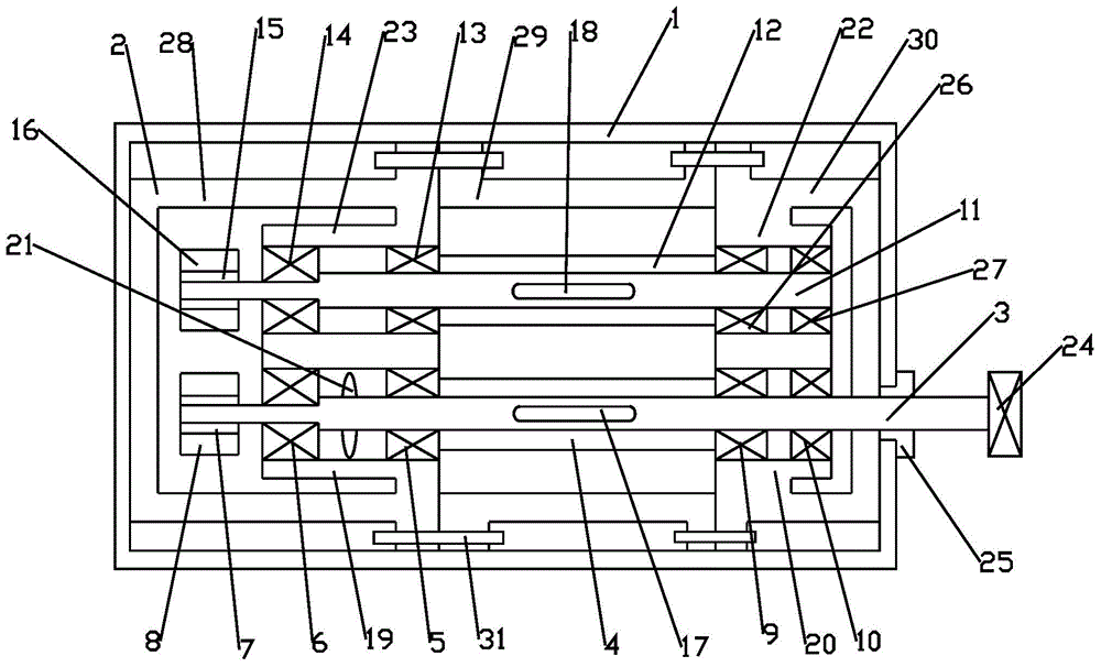
[0018] This embodiment includes a housing 2, the housing 2 is covered with a dustproof box 1, the housing 2 is provided with a driving shaft 3, the driving shaft 3 is covered with a driving impeller 4, and the side of the driving impeller 4 is provided with a first rear seal Ring 5, the first rear bearing 6, the first gear hub 7, the first rear seal ring 5 is located between the driving impeller 4 and the first rear bearing 6, the first rear bearing 6 is located between the first rear seal ring 5 and the first gear Between the hubs 7, the first gear hub 7 is covered with a first gear ring 8, and the other side of the driving impeller 4 is provided with a first front sealing ring 9 and a first front bearing 10, and the first front sealing ring 9 is located on the driving impeller 4 Between the first front bearing 10, the driving shaft 3 passes through the housing 2 and the dustproof box 1, and is connected with a coupling 24. An oil seal 25 is arranged between the driving shaft ...


PUM


Abstract

The invention belongs to the field of mechanical and electrical equipment and particularly relates to a double-shaft centrifugal fan. The double-shaft centrifugal fan comprises a shell; a driving shaft is arranged in the shell; a driven shaft is arranged above the driving shaft and covered with a driven impeller; second rear sealing rings, second rear bearings and second gear hubs are arranged on one side of the driven impeller; the second rear sealing rings are located between the driven impeller and the second rear bearings; the second rear bearings are located between the second rear sealing rings and the second gear hubs; the second gear hubs are sleeved with second gear rings; second front sealing rings and second front bearings are arranged on the other side of a driving impeller; the second front sealing rings are located between the driving impeller and the second front bearings; the driving shaft is provided with a first flat key; the driven shaft is provided with a second flat key; the shell comprises a front end cover, a connecting cover and a rear end cover; the front end cover and the connecting cover are connected through bolts; and the connecting cover and the rear end cover are in threaded connection.

Description

technical field [0001] The invention belongs to the field of electromechanical equipment, and in particular relates to a double-shaft centrifugal fan. Background technique [0002] Fan is the customary abbreviation for gas compression and gas conveying machinery in my country. Usually, fans include ventilators, blowers, and wind generators. Gas compression and gas delivery machinery are machines that convert rotational mechanical energy into gas pressure energy and kinetic energy, and transport the gas out. The main structural components of the fan are the impeller, casing, air inlet, bracket, motor, pulley, coupling, muffler, transmission parts (bearings), etc. The unpowered ventilator uses the natural wind force and the air heat convection caused by the temperature difference between indoor and outdoor to drive the turbine to rotate, so as to use centrifugal force and negative pressure effect to discharge the stale hot air in the room. Fans are related to the transmissio...

Claims


Application Information

Patent Timeline
IPC IPC(8): F04D17/08F04D29/08F04D29/00F04D29/42
Inventor 邵爱军
Owner 天津泽众智能设备有限公司
Why Eureka
Try Eureka