Stress application centrifugal pump with pressurization hole

A technology of booster hole and centrifugal pump, which is applied to the parts, pumps and pump elements of the pumping device for elastic fluids, can solve the problems of cavitation damage of the afterburner centrifugal pump, prolong the service life and ensure the operation. Safety and avoidance of cavitation damage

Inactive Publication Date: 2016-06-01
TSINGHUA UNIV
View PDF4 Cites 0 Cited by
  • Summary
  • Abstract
  • Description
  • Claims
  • Application Information

AI Technical Summary

Problems solved by technology

[0005] The purpose of the present invention is to solve the cavitation damage problem of the afterburning centrifugal pump, and propose a kind of afterburning centrifugal pump with a booster hole, which can suppress the occurrence of cavitation in th

Method used


Image

  • Stress application centrifugal pump with pressurization hole
  • Stress application centrifugal pump with pressurization hole
  • Stress application centrifugal pump with pressurization hole

Examples


Embodiment Construction

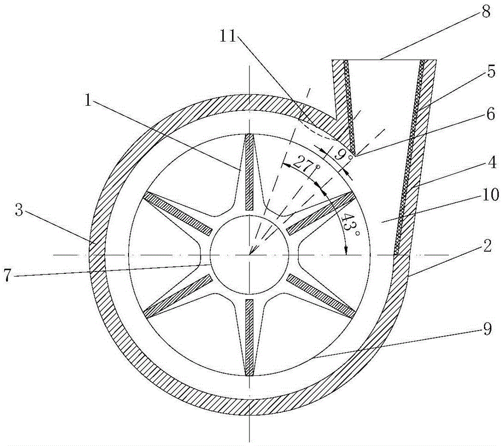
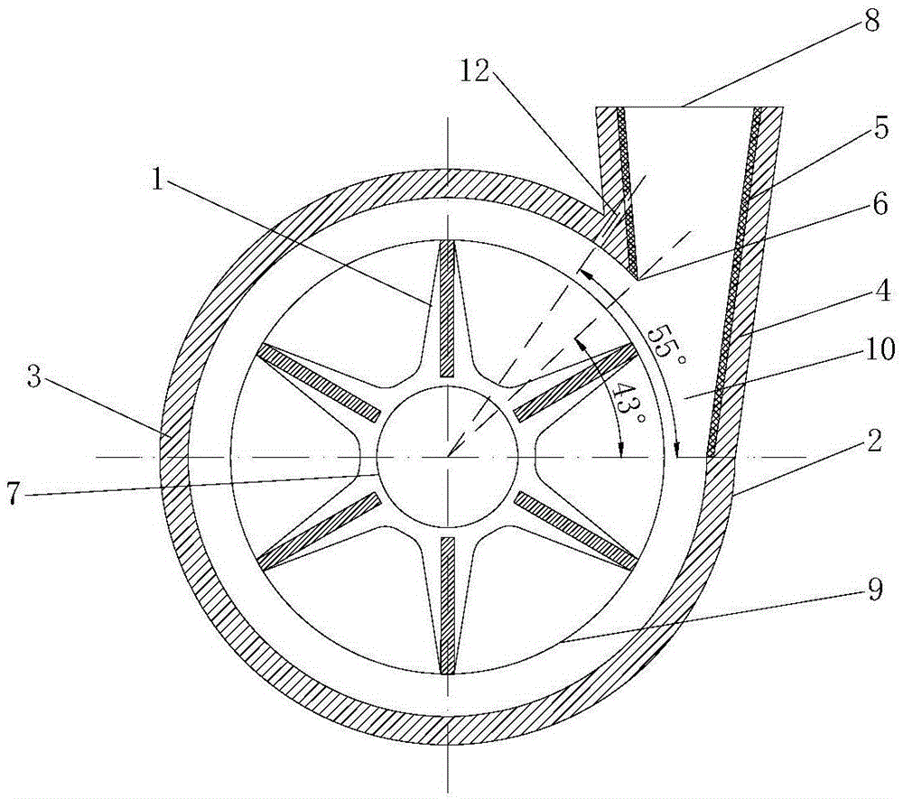
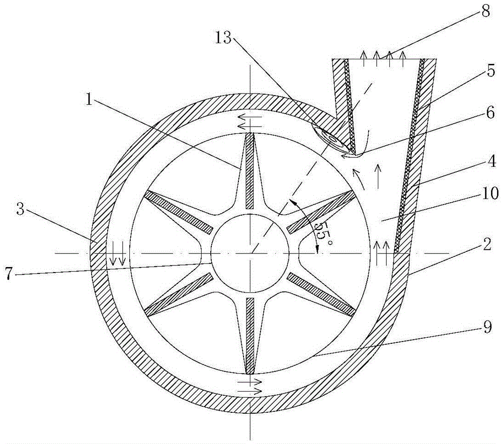
[0014] The present invention proposes a booster centrifugal pump structure with booster holes, such as figure 2 shown. The booster centrifugal pump is an improvement to the existing booster centrifugal pump, and is composed of an impeller 1 and a casing 2 , and the casing 2 includes a volute 3 and a diffuser tube 4 . The impeller 1 adopts a radial straight impeller, and the volute 3 adopts a concentric volute with a semicircular section shape, and the impeller 1 is installed in the volute 3 . The diffuser 4 is a conical diffuser, and the diffuser 4 communicates with the volute 3 . A tapered sleeve 5 is provided on the inner wall of the diffuser 4 . A partition tongue 6 is formed at the junction of the volute 3 and the tapered casing 5, and the installation angle of the partition tongue 6 is 43°. A pump inlet 7 concentric with the impeller is provided at the center of the volute 3 , the outlet of the diffuser pipe 4 is the pump outlet 8 , and the outline formed by the rotat...


PUM


Abstract

The invention discloses a stress application centrifugal pump with a pressurization hole and belongs to the field of stress application fuel systems of aircraft engines. The stress application centrifugal pump comprises a vane wheel and a shell, wherein the shell comprises a vortex chamber and a diffusion tube; the vane wheel is mounted in the vortex chamber; the diffusion tube is communicated with the vortex chamber; a conical casing tube is arranged on the inner wall of the diffusion tube; a volute tongue is formed in a boundary between the vortex chamber and the conical casing tube; the shell also comprises a pressurization hole; the pressurization hole is a circular through hole from the diffusion tube to the downstream of the volute tongue. The stress application centrifugal pump with the pressurization hole can effectively solve the problem of cavitation erosion damage caused by cavitation of the stress application centrifugal pump.

Description

technical field [0001] The invention belongs to the field of afterburner fuel systems of aero-engines, and in particular relates to a structural design of an afterburner centrifugal pump with booster holes, which can effectively solve the cavitation damage problem of the afterburner centrifugal pump caused by cavitation. Background technique [0002] The afterburner centrifugal pump is an important part of the afterburner fuel system of an aero-engine, and its function is to provide fuel with a certain pressure and flow to the afterburner fuel system. The existing afterburning centrifugal pump structure such as figure 1 As shown, it usually consists of impeller 1 and casing 2. The housing 2 includes a volute 3 and a diffuser 4 . The impeller 1 adopts a radial straight impeller, and the volute 3 adopts a concentric volute with a semicircular section shape, and the impeller 1 is installed in the volute 3 . The diffuser 4 is a conical diffuser, and the diffuser 4 communicate...

Claims


Application Information

Patent Timeline
IPC IPC(8): F04D29/42
CPCF04D29/426
Inventor 范红雨朴英
Owner TSINGHUA UNIV
Why Eureka
Try Eureka