Heat Exchanger

A heat exchanger and heat exchange unit technology, applied in evaporators/condensers, lighting and heating equipment, refrigeration components, etc., can solve the problems of large temperature difference and uneven air temperature, and achieve uniform and distributed air temperature. Uniform and high heat transfer efficiency

Inactive Publication Date: 2018-03-30
DANFOSS MICRO CHANNEL HEAT EXCHANGER JIAXING
View PDF8 Cites 2 Cited by
  • Summary
  • Abstract
  • Description
  • Claims
  • Application Information

AI Technical Summary

Problems solved by technology

[0012] exist image 3 In the prior art shown, half of the straight flat tubes 33 are used to input the working fluid to the second header 32, and the other half of the straight flat tubes 33 are used to output the working fluid from the second header 32. It will cause a large temperature difference between the upper straight flat tube 33 and the lower straight flat tube 33, which will lead to uneven outlet air temperature

Method used


Image

  • Heat Exchanger
  • Heat Exchanger
  • Heat Exchanger

Examples


no. 1 example

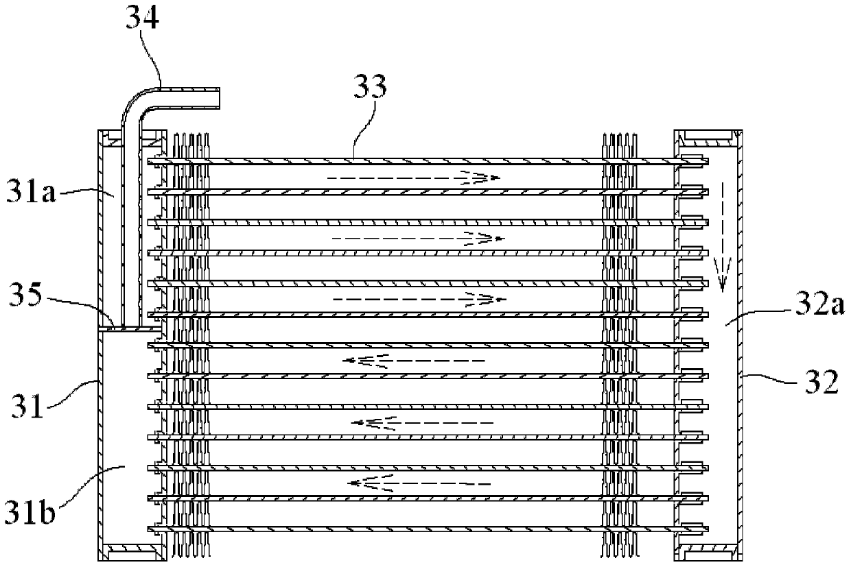
[0055] Figure 4 A schematic perspective view showing the heat exchanger 100 according to the first embodiment of the present invention; Figure 5 show Figure 4 A partially enlarged schematic diagram of the heat exchanger 100 shown; Figure 6 show Figure 4 and Figure 5 An enlarged schematic view of the connecting component 140 in .

[0056] Such as Figure 4 As shown, in the first embodiment of the present invention, a heat exchanger 100 is disclosed. The heat exchanger 100 mainly includes an inlet header 111, a first header 121, and a second header 122. , an outlet pipe 112 , a plurality of first flat pipes 131 , a plurality of second flat pipes 132 and a communication part 140 .

[0057] Please continue to see Figure 4 , in the illustrated embodiment, the inlet header 111 and the first header 121 are in fluid communication with each other through a plurality of first flat tubes 131, and the outlet tube 112 and the second header 122 are in fluid communication with ...

no. 2 example

[0071] Figure 7 A schematic perspective view showing a heat exchanger according to a second embodiment of the present invention; Figure 8 show Figure 7 An enlarged schematic view of the connecting component 240 in .

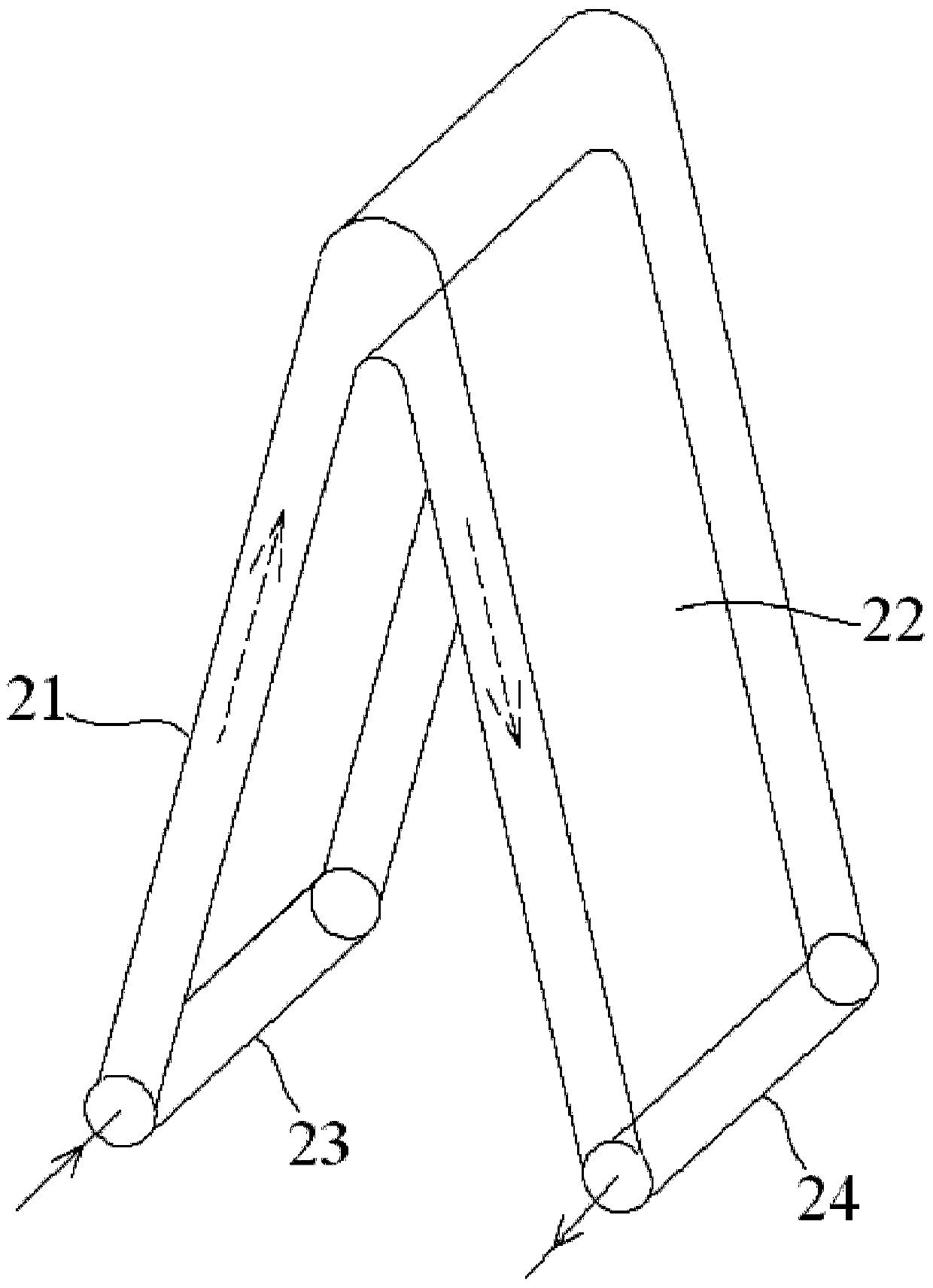
[0072] In the second embodiment of the present invention, as Figure 7 As shown, a heat exchanger is disclosed, which mainly includes two heat exchange units 210, 220 (the first heat exchange unit 210 and the second heat exchange unit 220). Each heat exchange unit 210, 220 includes a first tube 210a, 220a, a second tube 210b, 220b and an intermediate communication tube 211, 221 connecting the first tube 210a, 220a and the second tube 210b, 220b. In the illustrated embodiment, the intermediate communication pipes 211 and 221 are twisted flat pipes.

[0073] In one embodiment of the present invention, as Figure 7 and Figure 8 As shown, the communication part 240 includes a first branch pipe 241 , a second branch pipe 242 and a third branch pipe 243 which...

no. 3 example

[0086] Figure 11 shows a schematic diagram of a heat exchanger according to a third embodiment of the present invention; and Figure 12 show Figure 11 The enlarged schematic diagram of the communication part 340 in and the header 310 connected with the communication part 340 .

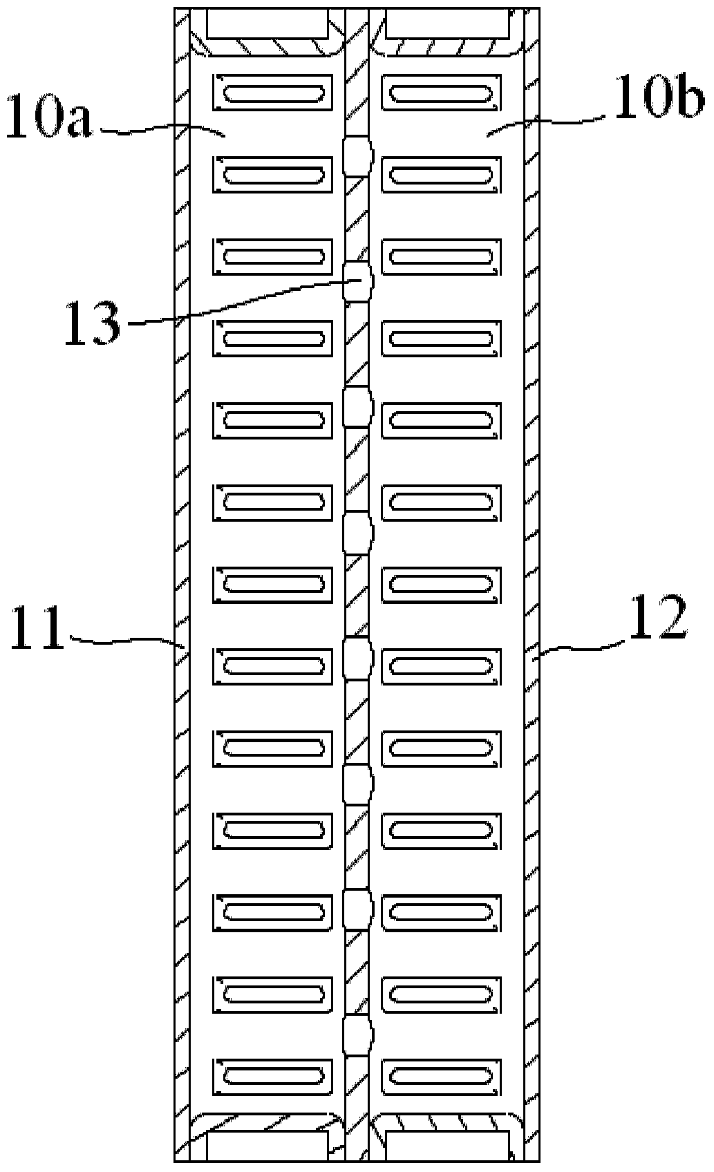
[0087] Such as Figure 11 and Figure 12 As shown, in the third embodiment, a heat exchanger is disclosed, which mainly includes a first header 310 , a second header 320 , a plurality of flat tubes 330 and a communication part 340 .

[0088] In one embodiment of the present invention, as Figure 11 and Figure 12 As shown, the inner space of the first header 310 is divided into a first chamber a, a second chamber b and a third chamber c by two partition plates 311, 312, wherein the third chamber c is located at the Between the first chamber a and the second chamber b.

[0089] In one embodiment of the present invention, as Figure 11 and Figure 12 As shown, the first chamber a, the second c...


PUM


Abstract

The invention discloses a heat exchanger, which has a first cavity and a second cavity, wherein the heat exchanger includes a communication part, and the communication part at least includes a first branch pipe and a second branch pipe communicated with each other , the first branch tube and the second branch tube are respectively inserted into the first cavity and the second cavity, and on the insertion parts of the first branch tube and the second branch tube A plurality of micropores are respectively formed for fluid communication between the first cavity and the second cavity. In the present invention, since the two internal cavities of the heat exchanger are in fluid communication only through a single communication component, the manufacturing cost of the heat exchanger is reduced and the sealing reliability of the heat exchanger is improved.

Description

technical field [0001] The present invention relates to a heat exchanger, in particular to a microchannel heat exchanger. The microchannel heat exchanger may be an all-aluminum microchannel heat exchanger, which is mainly used in HVAC, automobile, refrigeration and transportation fields. For parallel flow evaporators, heat pumps, etc. Background technique [0002] figure 1 A schematic showing the two headers of the first existing heat exchanger. [0003] Such as figure 1 As shown, the inner cavity 10 a of the header 11 and the inner cavity 10 b of the header 12 are in fluid communication with each other through a plurality of micro-flow tubes 13 . [0004] exist figure 1 In the prior art shown, the two ends of each microfluidic tube 13 are welded to the header 11 and the header 12 respectively. Thus, in figure 1 In the prior art shown, two welding points are added for every additional micro-flow tube 13, which will increase the risk of working fluid leakage, and multip...

Claims


Application Information

Patent Timeline
Patent Type & Authority Patents(China)
IPC IPC(8): F25B39/00F25B39/02
Inventor 金俊峰吴广生
Owner DANFOSS MICRO CHANNEL HEAT EXCHANGER JIAXING
Why Eureka
Try Eureka