Cross wind recycling type wet cooling tower

A wet-cooling tower and cross-wind technology, applied in the direction of water shower coolers, direct contact heat exchangers, heat exchange equipment, etc., can solve the problems of transformation and utilization, achieve enhanced heat dissipation, enhanced ventilation characteristics and cooling performance, and improved Effect of Circumferential Uniformity

Inactive Publication Date: 2016-06-01
TSINGHUA UNIV +2
View PDF8 Cites 4 Cited by
  • Summary
  • Abstract
  • Description
  • Claims
  • Application Information

AI Technical Summary

Problems solved by technology

However, judging from the relevant research results, so far, there is no good solution to convert and utilize the natural kineti

Method used


Image

  • Cross wind recycling type wet cooling tower
  • Cross wind recycling type wet cooling tower
  • Cross wind recycling type wet cooling tower

Examples


Example Embodiment

[0018] The working principle, specific structure and implementation of the present invention will be further explained below in conjunction with the accompanying drawings:

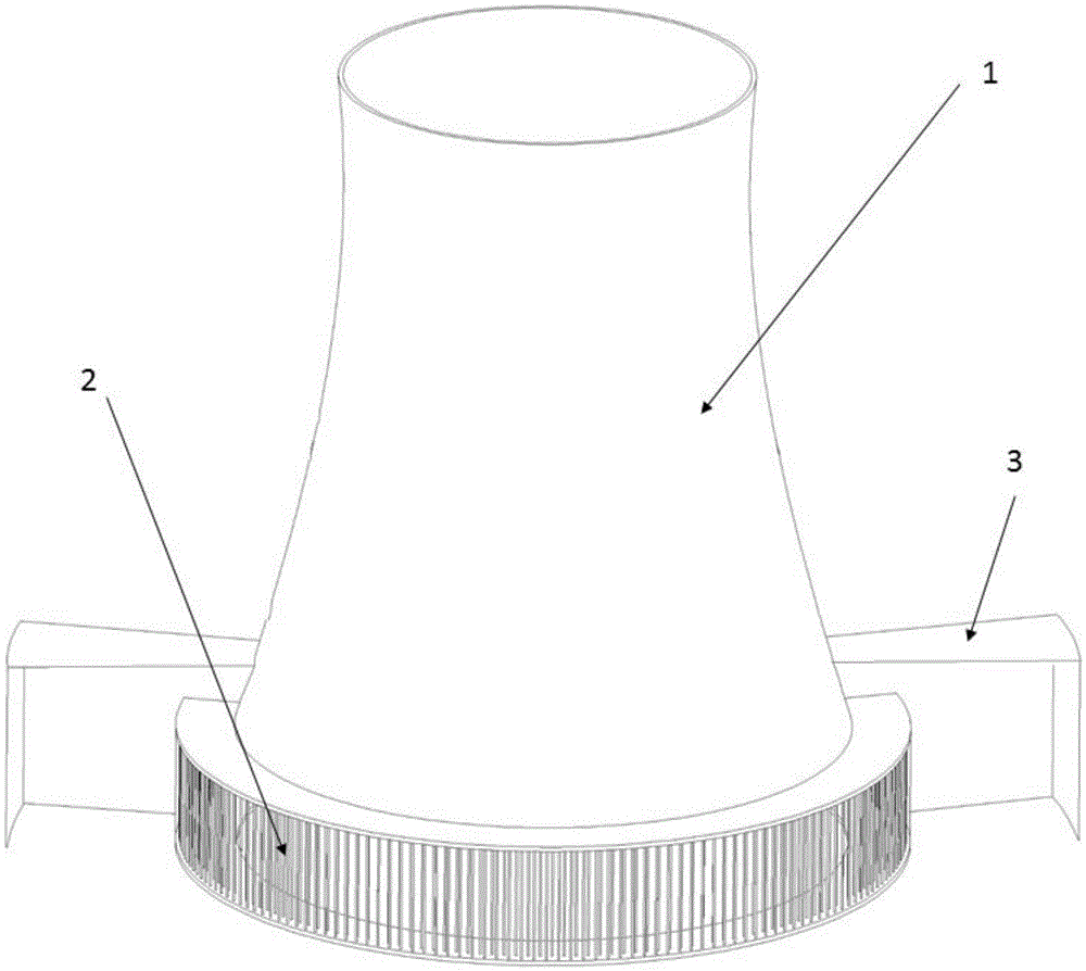
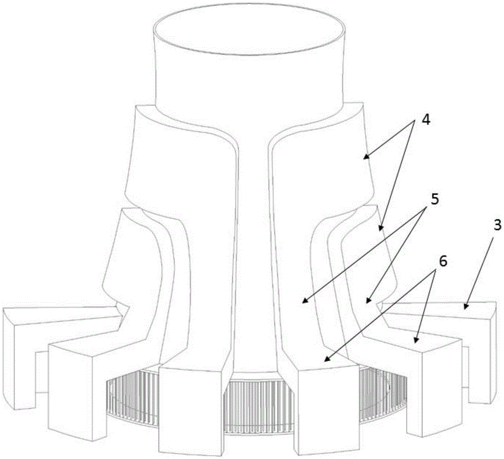
[0019] figure 1 It is a structural schematic diagram (front view of the windward side) of an embodiment of a wet cooling tower with a wind receiving chamber installed in the present invention. The wet cooling tower includes a wet cooling tower shell 1 and a bottom air inlet 2 and at least one winder arranged outside the bottom air inlet The wind chamber 3 is arranged along the circumference of the wet cooling tower. The wind chamber 3 is open facing the direction of the ambient wind and closed on the leeward side. Two wind-receiving devices are preferably arranged on both sides of the wet cooling tower. The height of the upper edge, the width of the lateral extension and the depth along the wind direction of the wind-receiving chamber can be comprehensively adjusted according to the demand for wind-receiving ...


PUM


Abstract

The invention discloses a cross wind recycling type wet cooling tower, in particular to a device for conducting flow guide utilization on environmental wind of a wet cooling unit of a power station. The wet cooling tower comprises a wet cooling tower shell, a bottom wind inlet and at least one wind collecting room arranged on the outer side of the bottom wind inlet. The wind collecting rooms are arranged in the circumferential direction of the wet cooling tower and are opened in the incoming flow direction of the environmental wind and are closed on the leeward side. At least one cross wind flow guide structure is arranged on the leeward side of the wet cooling tower. Each cross wind flow guide structure comprises an inlet wind flow guide section, a ventilation pipeline and a back outlet wind flow guide section, wherein the inlet wind flow guide section is opened in the incoming wind direction and is arranged on the upper side of the corresponding wind collecting room along the wet cooling tower shell. By means of the cross wind recycling tower wet cooling tower, due to the arrangement of the wind collecting rooms, the cross wind flow guide structures, wind blocking walls and the like, power sources of environmental cross wind are circumferentially arranged, the circumferential uniformity of inlet wind at the bottom of the wet cooling tower under the environmental wind condition is improved, a flow field structure in the wet cooling tower under the cross wind environment is improved, and therefore the ventilation characteristic and the cooling performance of the wet cooling tower are further enhanced.

Description

technical field [0001] The invention relates to a structural design of a cooling tower, in particular to a device for guiding and utilizing the ambient wind of a wet-cooling unit in a power plant, and belongs to the technical field of cooling equipment. Background technique [0002] The wet cooling tower is the key equipment of the wet cooling unit in the power plant, and it is a necessary condition to establish the vacuum of the steam turbine and take away the heat source at the cold end. However, due to the existence of environmental crosswinds and the uncontrollability of its direction and wind speed, it has brought great challenges to the economical, safe and stable operation of the unit. [0003] The environmental side wind will mainly destroy the pressure field and flow field environment at the inlet and outlet of the wet cooling tower, form a vortex flow inside the wet cooling tower, and deflect the airflow at the outlet of the wet cooling tower, resulting in a reduct...

Claims


Application Information

Patent Timeline
IPC IPC(8): F28C1/00F28F25/10
CPCF28C1/00F28F25/10F28F2250/102
Inventor 王卫良李政刘建民倪维斗李永生
Owner TSINGHUA UNIV
Why Eureka
Try Eureka