Dynamic demonstration model of petroleum drilling well control device

An oil drilling and dynamic technology, which is applied in the field of oil drilling teaching, can solve the problems that students cannot fully understand the working principle and operation of well control equipment, cannot troubleshoot timely, and students can intuitively view, etc.

Active Publication Date: 2016-06-01
TIANJIN LUYA SCI & TECH CO LTD
View PDF14 Cites 9 Cited by
  • Summary
  • Abstract
  • Description
  • Claims
  • Application Information

AI Technical Summary

Problems solved by technology

[0003] For the existing well control equipment training, three forms are adopted. The first is the teaching material training in the form of pictures, texts and videos. This form of training cannot allow the trainees to master the actual operation of the well control equipment, thus posing potential safety hazards; The second is the actual on-site operation training. Although this form of training can solve the actual operation mode of the trainees, due to the large size of the on-site well control equipment and the distribution of the well control equipment in different positions on the site, it is impossible for the trainees to fully observe each The overall operation status of the equipment makes it impossible to truly understand its working principle, and it is impossible to troubleshoot in time when an emergency occurs; the third is the developed well control model. Although the existing model has been reduced, it can be placed indoors for

Method used


Image

  • Dynamic demonstration model of petroleum drilling well control device
  • Dynamic demonstration model of petroleum drilling well control device
  • Dynamic demonstration model of petroleum drilling well control device

Examples


Embodiment Construction

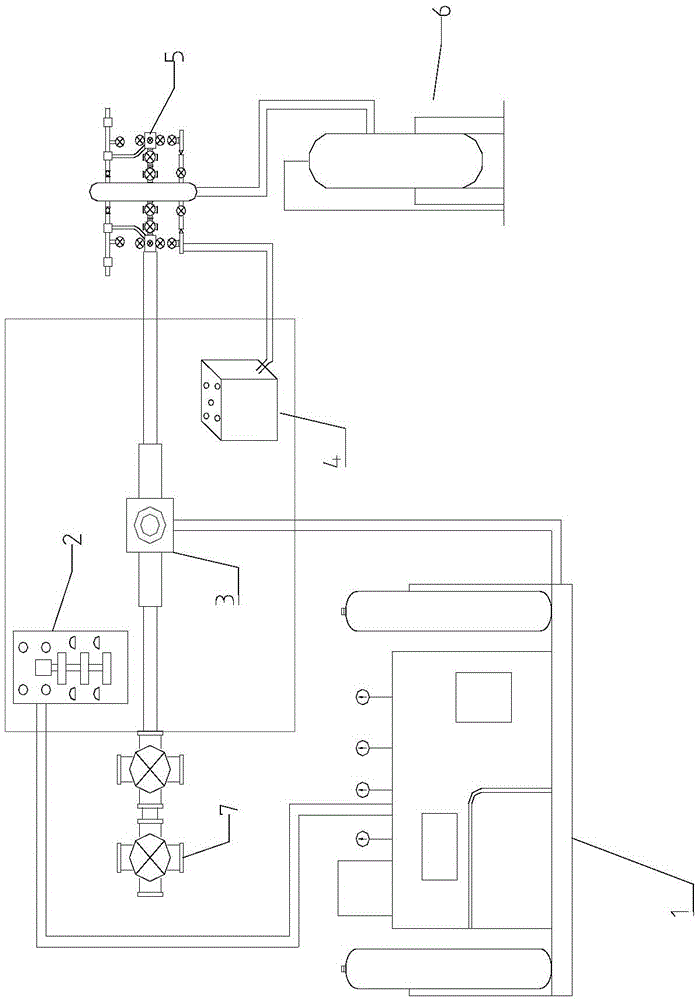
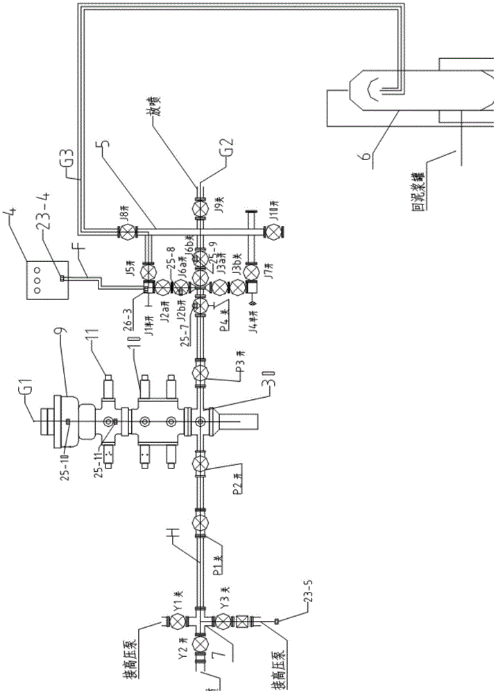
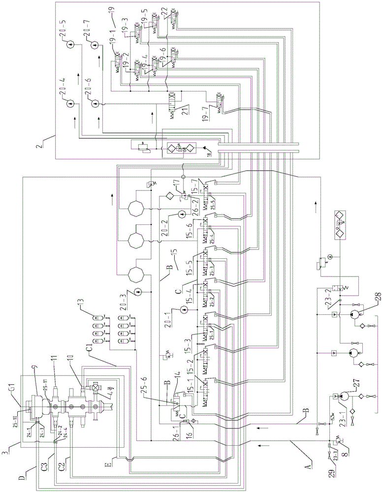
[0027] The following combination Figure 1~3 and specific embodiments describe the technical solution of the present invention in detail.

[0028] A dynamic demonstration model of an oil drilling well control device installed on a simulated rig floor, including a driller's console 2, a remote console 1, a choke manifold control box 4, and a liquid-gas separator 6 connected in sequence, a choke Manifold 5, blowout preventer group 3 and kill manifold 7; and the choke manifold 5, blowout preventer group 3 and kill manifold 7 are respectively installed at different interfaces of the drilling spool 30; The driller console 2 is connected to the remote console 1; the remote console 1 is connected to the blowout preventer group 3; the choke manifold control box 4 is connected to the choke manifold 5; the blowout preventer Group 3 is composed of annular blowout preventer 9, single ram blowout preventer 11 and double ram blowout preventer 10 arranged in sequence from top to bottom, and...


PUM


Abstract

The present invention discloses a dynamic demonstration model of a petroleum drilling well control device. The dynamic demonstration model of the petroleum drilling well control device comprises a driller's console, a remote console, a throttle manifold control cabinet, and a liquid-gas separator, a throttle manifold, a blowout preventer stack and a kill manifold which are connected in order; the throttle manifold, the blowout preventer stack and the kill manifold are respectively installed at different interfaces of a drilling spool; the driller's console is connected with the remote console; the remote console is connected with the blowout preventer stack through a transparent pipeline, and the blowout preventer stack is internally provided with a light band G1; the throttle manifold control cabinet is connected with the throttle manifold; the three-position four-way air rotary valve and the two-position four-way slide valve of the driller's console are able to pass through the three-position four-way change valves of an air control remote console to control the switch of the blowout preventer stack; the lamp strip is arranged in the associated line of the remote console and the blowout preventer stack; and proximity switches are arranged in the three-position four-way change valves to control the switching of the lamp strip. The dynamic demonstration model of a petroleum drilling well control device is able to visually demonstrate the actual running condition of the device in different work states and improve the operation safety.

Description

technical field [0001] The invention relates to the field of petroleum drilling teaching, in particular to a dynamic demonstration model of a petroleum drilling well control device. Background technique [0002] In oil drilling, well control equipment is a complete set of special equipment, instruments and tools for implementing oil and gas well pressure control technology. Well control equipment is an important equipment for detecting overflow in time when the formation pressure exceeds the drilling fluid column pressure, controlling the pressure in the well, avoiding and eliminating overflow, and preventing blowout and out-of-control blowout accidents. Therefore, well control training for drilling personnel has become a compulsory course for drilling workers. [0003] For the existing well control equipment training, three forms are adopted. The first is the teaching material training in the form of pictures, texts and videos. This form of training cannot allow the traine...

Claims


Application Information

Patent Timeline
IPC IPC(8): G09B25/02
CPCG09B25/02
Inventor 蒋新高志和闫金杰张勇周雪菡李健王玲明金峰黄丽君边双宾刘建超
Owner TIANJIN LUYA SCI & TECH CO LTD
Why Eureka
Try Eureka