Variable stiffness joint hydraulic driving system for exoskeleton robot

An exoskeleton robot and drive system technology, which is applied in manipulators, program-controlled manipulators, manufacturing tools, etc., can solve the problems of non-adjustable hydraulic cylinder stiffness, multiple oil pipe joints, and oil leakage, so as to improve wearing comfort and realize The effect of driving variable stiffness and reducing power output

Active Publication Date: 2021-08-10
芜湖云擎机器人科技有限公司
View PDF9 Cites 0 Cited by
  • Summary
  • Abstract
  • Description
  • Claims
  • Application Information

AI Technical Summary

Problems solved by technology

However, matching a hydraulic base station at each joint of the lower extremity exoskeleton increases the complexity of the joints, and the distributed power source is only composed of a motor, a pump, and an oil tank, and the flow rate of the hydraulic cylinder is controlled by the speed of the motor, which reduces the control accuracy of the hydraulic system
Chinese Patent No. 201310137055.2 "A Highly Integrated Hydraulic Drive Unit Structure" discloses a highly integrated double-rod hydraulic cylinder, which integrates servo valves, oil circuit connecting blocks, force sensors and displacement sensors into the hydraulic cylinder, shortening the The distance between the servo valve and the hydraulic cylinder is increased, but because the hydraulic base station is not integrated, the entire exoskeleton system still uses a single hydraulic base station, with many oil pipes and oil pipe joints, and the risk of oil leakage still exists
At the same time, in the above four patents, a double oil port hydraulic cylinder is used, and the rigidity of the hydraulic cylinder cannot be adjusted.
In the ground contact and bounce phases of the exoskeleton walking process, the soles of the human body contact the ground quickly, and the hydraulic cylinder cannot be flexibly adjusted according to the external load, which will cause the human body to touch the ground or bounce up stiffly, making the human body uncomfortable for walking

Method used


Image

  • Variable stiffness joint hydraulic driving system for exoskeleton robot
  • Variable stiffness joint hydraulic driving system for exoskeleton robot
  • Variable stiffness joint hydraulic driving system for exoskeleton robot

Examples


Embodiment Construction

[0021] In order to make the technical means, creative features, goals and effects achieved by the present invention easy to understand, the present invention will be further elaborated below.

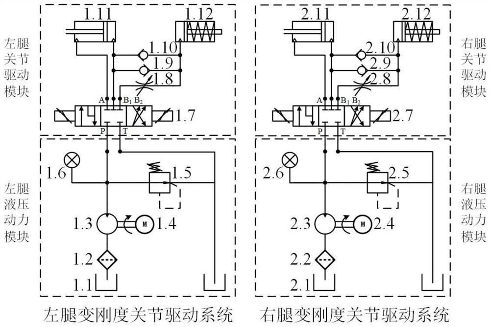
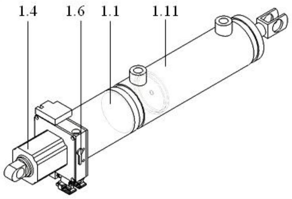
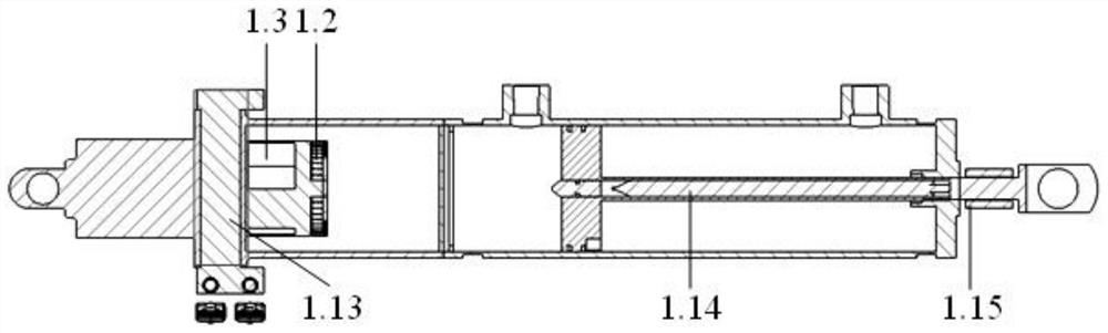
[0022] Such as Figure 1 to Figure 7 As shown, it includes the left leg variable stiffness joint drive system and the right leg variable stiffness joint drive system respectively used to drive the left leg and the right leg with the same internal structure. The drive system includes a hydraulic power module and a joint drive module that assists in driving the human body to walk .

[0023] The present invention uses a distributed power source to replace the centralized hydraulic power source in the exoskeleton backpack, which solves the risk of oil leakage caused by a large number of oil pipes and oil pipe joints in the centralized hydraulic power source, reduces the complexity of system control, and simultaneously integrates the centralized The hydraulic power source is decomposed into...


PUM


Abstract

The invention relates to the field of hydraulic driving systems, in particular to a variable stiffness joint hydraulic driving system for an exoskeleton robot. The variable stiffness joint hydraulic driving system comprises a left leg variable stiffness joint driving system and a right leg variable stiffness joint driving system which are respectively used for driving a left leg and a right leg and have the same internal structure, wherein each driving system comprises a hydraulic power module and a joint driving module for assisting in driving a human body to walk. According to the variable stiffness joint hydraulic driving system, a distributed power source is adopted to replace a centralized hydraulic power source in an exoskeleton backpack, the oil leakage risk caused by more oil pipes and oil pipe joints of the centralized hydraulic power source is solved, the complexity of system control is reduced, meanwhile, the centralized hydraulic power source is decomposed into a distributed hydraulic power source, a common bearing backpack of a hydraulic drive type lower limb exoskeleton can be replaced, the backpack-free mode is achieved, and the overall structure is more concise.

Description

technical field [0001] The invention relates to the field of hydraulic drive systems, in particular to a variable stiffness joint hydraulic drive system for exoskeleton robots. Background technique [0002] With the aging population in our country, the increase in the number of strokes, frequent traffic accidents and other reasons, the number of patients with lower limb motor dysfunction is increasing. Therefore, wearable lower limb exoskeleton robot, as an intelligent device that can assist the movement of human lower limbs, has become a demand for social development. [0003] At present, the joint drive methods of lower extremity exoskeleton robots mainly adopt motor drive and hydraulic drive. Motor drive is currently the most widely used driving method in lower extremity exoskeleton research. It is usually arranged in a direction parallel to the leg members of the lower extremity exoskeleton, and the motion transmission is realized through transmission devices such as ge...

Claims


Application Information

Patent Timeline
Patent Type & Authority Applications(China)
IPC IPC(8): B25J9/14B25J9/00
CPCB25J9/14B25J9/0006
Inventor 汪步云吴臣许德章汪志红季景
Owner 芜湖云擎机器人科技有限公司
Why Eureka
Try Eureka