
Air cylinder head and engine

A cylinder head and cylinder head technology, applied in the direction of engine components, machines/engines, cylinders, etc., can solve the problems of complex production process, cumbersome assembly, and difficult machining of cylinder heads, etc., to achieve compact structure, simplify assembly process, avoid The effect of oil spill risk

Pending Publication Date: 2018-06-08
CHONGQING LONCIN ENGINE +1
View PDF0 Cites 0 Cited by
  • Summary
  • Abstract
  • Description
  • Claims
  • Application Information

AI Technical Summary

Problems solved by technology

[0003] Under the premise of satisfying the machining of the rocker arm shaft hole, the installation hole of the camshaft limit plate, and the installation of the water pump assembly, the existing engine makes it difficult to machine the cylinder head, the production process is complicated, and the assembly is cumbersome

Method used


Image

  • Air cylinder head and engine
  • Air cylinder head and engine
  • Air cylinder head and engine

Examples


Embodiment 1

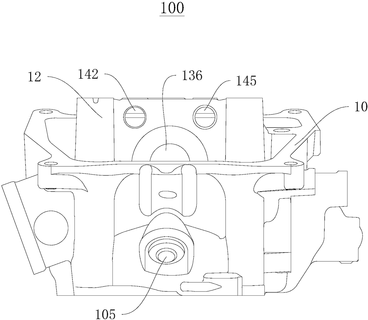
[0046] figure 1 A schematic structural view of the cylinder head 100 provided in this embodiment at a first viewing angle. Please refer to figure 1 shown. The cylinder head 100 includes an integrally formed cylinder head base 10 and a support base 12 , wherein the support base 12 is located inside the cylinder head base 10 , and the support base 12 and the cylinder head base 10 form a cavity.

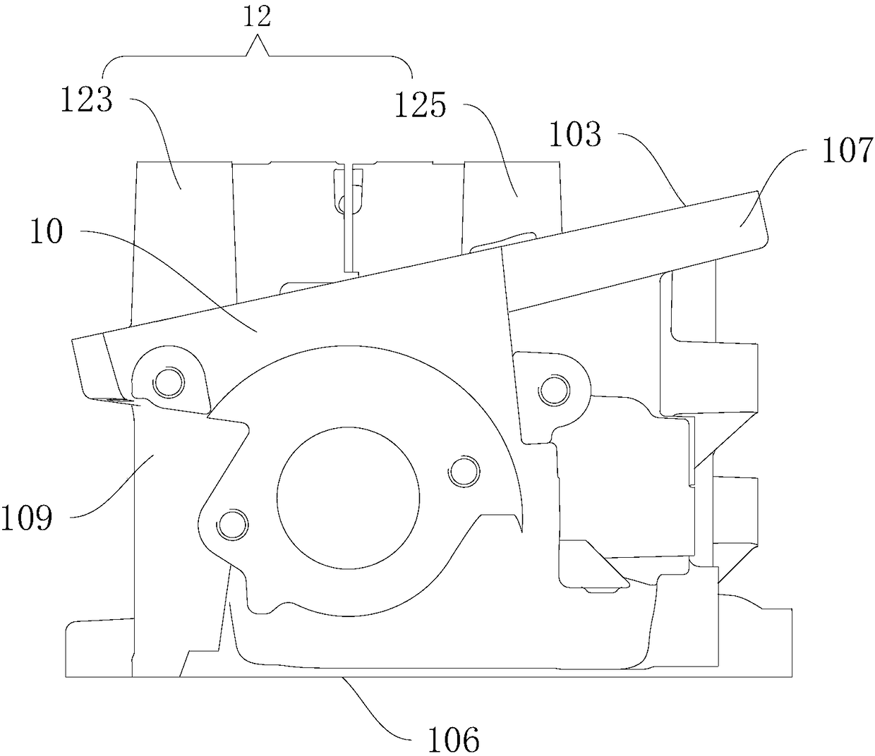
[0047] figure 2 A schematic structural diagram of the cylinder head 100 provided in the second viewing angle for this embodiment. Please refer to figure 2 shown. The cylinder head base 10 includes opposite first installation surfaces 103 and second installation surfaces 106, wherein the first installation surface 103 is located at the top of the cylinder head base 10, the second installation surface 106 is located at the bottom of the cylinder head base 10, and the cylinder head base 10 During installation, the second mounting surface 106 is matched with the cylinder block, the ...

Embodiment 2

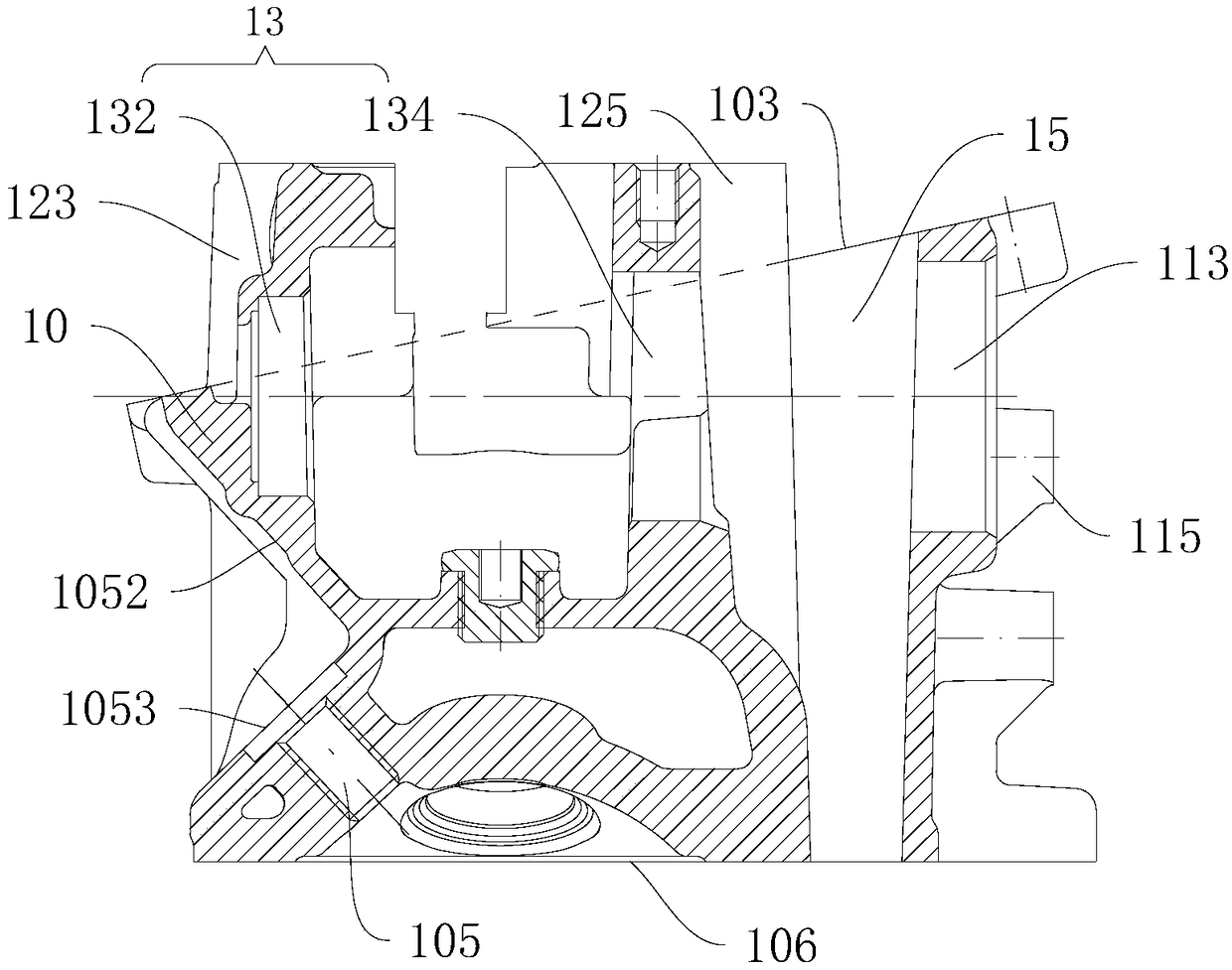
[0071] Embodiment 2 provides an engine, including a camshaft assembly 18, a rocker arm assembly, a water pump assembly 16, a spark plug assembly 17, and the cylinder head 100 provided in Embodiment 1, Image 6 A cross-sectional view of the engine is provided for Example 2. Please refer to Image 6 shown.

[0072] The spark plug assembly 17 is fixedly arranged in the spark plug installation hole 105, and the leaking part of the spark plug assembly 17 is just located in the accommodation space of the lower side 109 of the cylinder head base 10, which is convenient for assembly and does not interfere.

[0073] The camshaft assembly 18 is fixedly arranged on the camshaft mounting portion 13 of the support base 12. Specifically, the first bearing is embedded in the first camshaft mounting hole 132, and the second bearing is embedded in the second camshaft mounting hole 134. The first bearing and the second bearing are coaxially arranged, and the water pump assembly 16 is embedded...


PUM


Abstract

The invention discloses an air cylinder head and an engine, relating to the technical field of engines. The air cylinder head comprises a cylinder head matrix and a support seat which are integrally formed, wherein the support seat is located in the cylinder head matrix and forms a mold cavity with the cylinder head matrix; the cylinder head matrix comprises a first mounting surface and a second mounting surface, the first mounting surface is located at the top of the cylinder head matrix and is fixedly connected with an air cylinder cover, the second mounting surface is located at the bottomof the cylinder head matrix and is fixedly connected with an air cylinder body, and the first mounting surface is obliquely arranged relative to the second mounting surface to enable the cylinder headmatrix to form relatively high and low sides; and a perforated chain cavity is formed in the high side and is located between the cylinder head matrix and the support seat, and a sparking plug mounting hole is formed in the lower side, is located on one side, close to the second mounting surface, of the cylinder head matrix and is obliquely formed relative to the second mounting surface. The aircylinder head is reasonable in design and convenient to produce, manufacture and assemble, the production difficulty is greatly reduced, the production and assembling processes are simplified, and theproduction cost is lowered.

Description

technical field [0001] The invention relates to the technical field of engines, in particular to a cylinder head and an engine. Background technique [0002] Water cooling is to use water (or antifreeze) as a cooling medium to take away the heat from high-temperature parts of the engine to ensure the normal operating temperature of the engine. The water cooling system consists of water pumps, radiators, fans, thermostats, water jackets and water pipes. The coolant of the water-cooling system is in the water jacket of the engine. After absorbing the heat of the high-temperature parts, the temperature rises. The radiator is cooled by the fan and the windward airflow, and then the cooled coolant is pumped into the water jacket for circulating cooling. [0003] Under the premise of satisfying the processing of the rocker shaft hole, the mounting hole of the camshaft limit plate and the installation of the water pump assembly in the existing engine, it is difficult to machine th...

Claims


Application Information

Patent Timeline
Patent Type & Authority Applications(China)
IPC IPC(8): F02F1/00
CPCF02F1/00
Inventor 陈志敏陈俊儒程仕杰刘建宇陈前程
Owner CHONGQING LONCIN ENGINE
Learn More