Piezoelectric energy collection rectifier for open-circuit type optimization of turnover time

A technology of inversion time and piezoelectric energy, applied in piezoelectric effect/electrostrictive or magnetostrictive motors, irreversible AC power input conversion to DC power output, electrical components and other directions, which can solve the problem of reducing switch on-time Rectifier extraction efficiency, limiting the output voltage amplitude of the piezoelectric terminal, increasing the conduction loss, etc., to achieve the effect of optimizing the switch conduction time, reducing power consumption, and increasing net energy

Inactive Publication Date: 2016-06-01
HUNAN UNIV
View PDF6 Cites 8 Cited by
  • Summary
  • Abstract
  • Description
  • Claims
  • Application Information

AI Technical Summary

Problems solved by technology

[0005] although figure 2 The circuit shown solves the problem of charge waste, but it uses a passive diode, which increases the conduction loss and limits the output voltage range of the piezoelectric terminal, and the conduction time of the switch is affected by the inductance, the capacitance of the piezoelectric terminal, and even the load. Influence, the precise control of the conduction time requires additional manual adjustment, and the unsuitable switch conduction time will greatly reduce the extraction efficiency of the rectifier
Considering these issues, this circuit is not suitable for small piezoelectric energy harvesting

Method used


Image

  • Piezoelectric energy collection rectifier for open-circuit type optimization of turnover time
  • Piezoelectric energy collection rectifier for open-circuit type optimization of turnover time
  • Piezoelectric energy collection rectifier for open-circuit type optimization of turnover time

Examples


Embodiment Construction

[0016] The present invention will be described in further detail below in conjunction with the accompanying drawings and specific implementation.

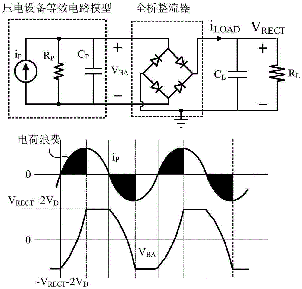
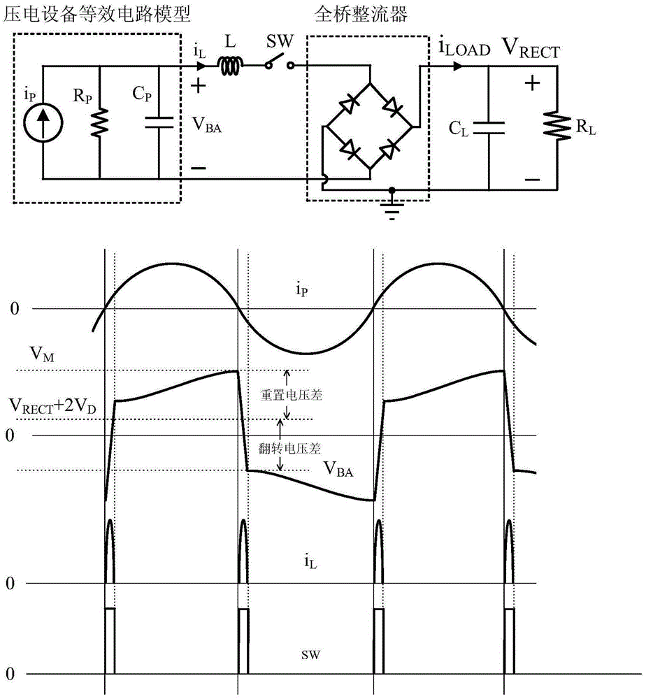
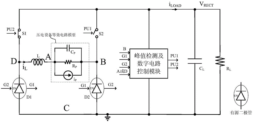
[0017] like figure 1 , figure 2 and image 3 As shown, the piezoelectric conductor is equivalent to a circuit model that includes a current source i in parallel P , a resistor R P and a capacitor C P . Suppose the current source can be expressed as

[0018] i P =I P sin(2πf P t)(1)

[0019] where the current amplitude I P It is related to the acceleration of the vibration source, f P Corresponding to the vibration frequency of the vibration source. In addition, because the resistor R P The value of is very large in megabytes, so it can be ignored in the analysis, and the load capacitance C is assumed L The value is large, making V RECT It can be regarded as a stable DC voltage.

[0020] image 3 Shown is the rectifier of the present invention, its basic operation principle can refer to Figure 4 , before time t3,...


PUM


Abstract

The invention discloses a piezoelectric energy collection rectifier for open-circuit type optimization of turnover time. The piezoelectric energy collection rectifier comprises two active diodes, two switches, an inductor and a peak detection and digital circuit control module, wherein a pair of active diodes carries out complementary conduction/stop operation; once one diode detects a zero crossing point flowing through a current from a positive electrode to a negative electrode, the diode is turned off and opposite the other diode is turned on; each active diode outputs a corresponding on-off state signal; the peak detection and digital circuit control module receives the on-off state signal of each active diode, detects a voltage peak of a cathode of the active diode and outputs a pulse signal of the optimized pulse width; the two switches receive the pulse signal of the peak detection and digital circuit control module and carry out on/off operation; and the inductor is connected with a piezoelectric device in series, and is connected to an input end of the rectifier. Under the control of the peak detection and digital circuit control module, the capacitor voltage of the piezoelectric device is optimally turned over; and meanwhile, the energy is transmitted to a load.

Description

technical field [0001] The invention mainly relates to the field of converting mechanical energy into electric energy, in particular to an open-circuit piezoelectric energy harvesting rectifier with optimized flipping time. Background technique [0002] Energy harvesters based on piezoelectric cantilever arm structures are very suitable for miniaturized vibration energy harvesting systems due to their low cost, high power density, and high scalability. However, the available power of miniaturized energy harvesting systems is very low, generally less than 1 milliwatt, and the losses caused in the energy transmission process further reduce the net energy to the load. Therefore, a low power consumption circuit design is essential. In addition, since the output voltage from the piezoelectric conductor is AC, and the load requires a stable DC voltage, an AC-to-DC rectifier is also required. [0003] figure 1 Represents a typical piezoelectric energy harvesting circuit using a ...

Claims


Application Information

Patent Timeline
Patent Type & Authority Applications(China)
IPC IPC(8): H02M7/12H02N2/18
CPCH02M7/12H02N2/181H02M1/0012
Inventor 邝继顺吴了尤志强凌纯清
Owner HUNAN UNIV
Why Eureka
Try Eureka