Vacuum-sealed structure and manufacturing method thereof

A technology of vacuum sealing structure and sealing plate, which is applied in the direction of sealed casing, electrical equipment casing/cabinet/drawer, electrical components, etc., which can solve the problems of polluting the vacuum cavity and large flange wall thickness, and reduce the area of ​​deflation , reduce the wall thickness, reduce the effect of the possibility of gas residue

Active Publication Date: 2018-09-11
INST OF MICROELECTRONICS CHINESE ACAD OF SCI
View PDF3 Cites 0 Cited by
  • Summary
  • Abstract
  • Description
  • Claims
  • Application Information

AI Technical Summary

Problems solved by technology

[0005] The invention is a vacuum sealing structure of a board-level electronics system, which is mainly used to solve the following technical problems: (1) When the existing vacuum sealing structure adopts non-metallic sealing components, the non-metallic sealing components themselves deflate to generate polluting gas , thereby polluting the vacuum cavity; (2) When the existing vacuum sealing structure adopts metal sealing components, the flange wall thickness is too large

Method used


Image

  • Vacuum-sealed structure and manufacturing method thereof
  • Vacuum-sealed structure and manufacturing method thereof
  • Vacuum-sealed structure and manufacturing method thereof

Examples


Embodiment Construction

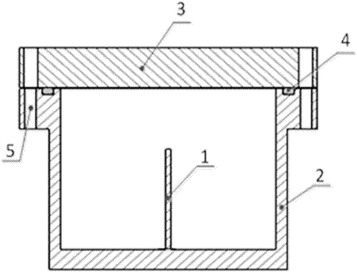
[0021] The present invention proposes a vacuum sealing structure and a manufacturing method thereof. The vacuum sealing structure can be applied to occasions where gas-releasing components need to be sealed. The gas-releasing components are, for example, board-level electronic systems for extreme ultraviolet lithography.

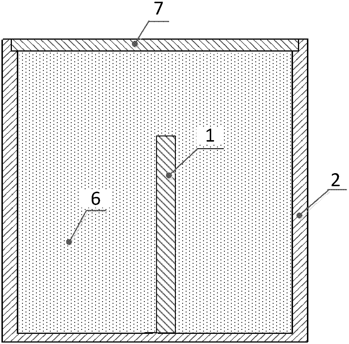
[0022] figure 2 It is a structural schematic diagram of the vacuum sealing structure of the present invention, such as figure 2 As shown, the vacuum-tight structure of the present invention includes a sealed casing 2 , a potting compound 6 and a sealing device 7 . The sealed housing 2 has a chamber, the chamber has a side wall and an open end, and is used to accommodate the deflation element 1; the potting compound 6 is filled in the chamber of the sealed housing 2 and wraps the deflation element 1. The sealing device 7 is used to close the opening end of the cavity of the sealed housing 2 and is in close contact with the potting compound 6 and the side w...


PUM


Abstract

The invention discloses a vacuum seal structure and a manufacturing method thereof. The vacuum seal structure comprises a seal shell (2), a potting adhesive (6) and a seal device (7), wherein the seal shell (2) comprises a chamber; the chamber comprises a lateral wall and an open end and is used for accommodating an air escape element (1); the potting adhesive (6) is filled into the chamber of the seal shell (2) and coats the air escape element (1); and the seal device (7) is used for sealing the open end of the chamber of the seal shell (2) and is in tight contact with the potting adhesive (6) and the lateral wall of the seal shell (2). A liquid low-melting point alloy covers the potting adhesive (6) and forms the seal plate (71) as the seal device (7) after being cooled and solidified. The vacuum seal structure can prevent a nonmetal seal element from escaping air to generate harmful air; the wall thickness of the vacuum seal structure is reduced; the air escape area of the vacuum seal structure is reduced; and the possibility of a residual gas is reduced.

Description

technical field [0001] The invention relates to a vacuum sealing structure, which is especially suitable for the vacuum sealing structure of an extreme ultraviolet lithography board-level electronic system. Background technique [0002] Extreme ultraviolet lithography (EUVL) is currently the most promising lithography technology in the world, which can meet the mass production of IC nodes below CD14nm. Since most gases absorb 13.5nm extreme ultraviolet light, especially hydrocarbons, water vapor and other gases decomposed under the action of extreme ultraviolet light, it will cause carbon deposition and oxidation of the multilayer film on the surface of the extreme ultraviolet mirror, which will affect the reflection rate, so it is necessary to provide a clean vacuum environment for the lithography machine. [0003] There are a large number of board-level electronic systems inside the extreme ultraviolet lithography machine. The PCB board and electronic components will rele...

Claims


Application Information

Patent Timeline
Patent Type & Authority Patents(China)
IPC IPC(8): H05K5/06
CPCH05K5/064
Inventor 王魁波张罗莎吴晓斌陈进新罗艳谢婉露周翊王宇
Owner INST OF MICROELECTRONICS CHINESE ACAD OF SCI
Why Eureka
Try Eureka