Swirling de-swirling coupled efficient dedusting and demisting assembly

A defogging component and derotation technology, which is applied in the field of flue gas purification, can solve the problems of large pressure loss, high dust removal and defogging efficiency, and small pressure loss of the cyclone plate dust removal and fog removal device, and achieves high dust removal and fog removal efficiency. No risk of fouling and clogging, low energy consumption

Active Publication Date: 2016-06-08
SHANGHAI JIAO TONG UNIV
View PDF6 Cites 11 Cited by
  • Summary
  • Abstract
  • Description
  • Claims
  • Application Information

AI Technical Summary

Problems solved by technology

[0005] The purpose of the present invention is to overcome the defects of the above-mentioned prior art and provide a dust removal and mist removal with high efficiency and small pressure loss, which can better realize the deep dust removal and removal of saturated wet flue gas containing a large number of liquid droplets after desulfurization. The swirl-race coupling high-efficiency dedusting and demisting component with fog effect is used to solve the technical problems such as large pressure loss of the existing swirling plate dedusting and demisting device

Method used


Image

  • Swirling de-swirling coupled efficient dedusting and demisting assembly
  • Swirling de-swirling coupled efficient dedusting and demisting assembly

Examples


Embodiment 1

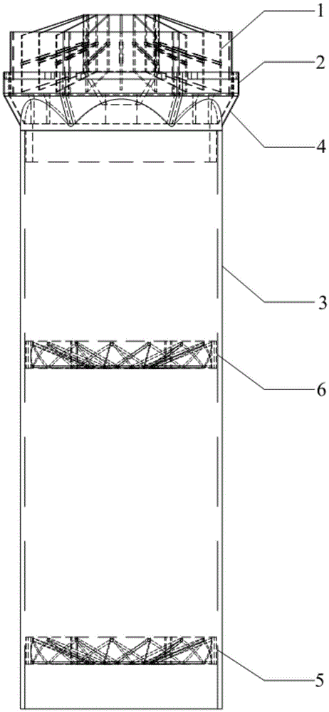
[0040] Such as figure 1As shown, a swirl-race coupling high-efficiency dedusting and mist removal assembly is arranged above the spray layer in the desulfurization absorption tower and includes multiple dust and mist removal units. The dust and mist removal units include an outer cylinder, a From bottom to top, the first-stage centrifugal swirl plate 5, the second-stage centrifugal swirl plate 6, and the racemic hydrophobic plate 1 obliquely arranged on the top of the outer cylinder are arranged in parallel in the outer cylinder body. The first-stage centrifugal swirl plate There is a gap between the outer edge of the plate 5, the outer edge of the second-stage centrifugal swirl plate 6 and the inner wall of the outer cylinder.

[0041] Wherein, the outer cylinder is composed of an upper cylinder 2 with a regular hexagonal cross-section, a cylindrical lower cylinder 3, and a transition pipe 4 arranged between the upper cylinder 2 and the cylindrical lower cylinder 3. The racem...

Embodiment 2

[0050] In this embodiment, the cross section of the upper cylinder 2 of the outer cylinder is a regular hexagon, and the diameter of the circumscribed circle of the upper cylinder 2 is 400 mm, and the outer diameter of the cylindrical lower cylinder 3 is 300 mm.

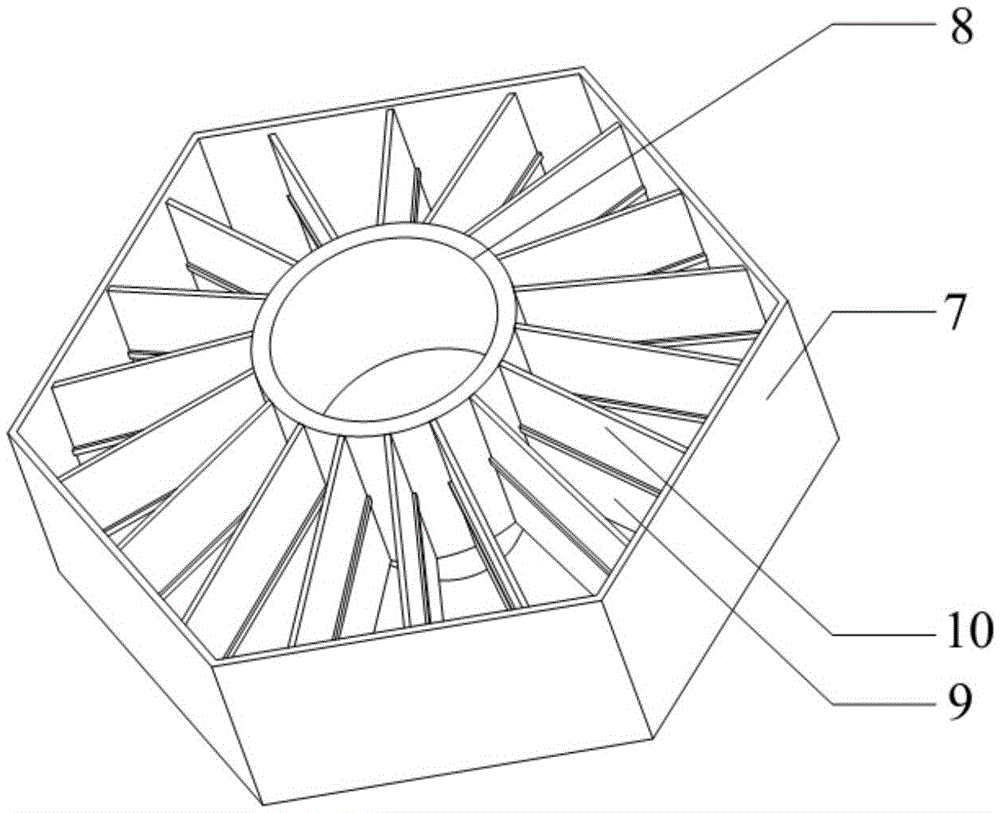
[0051] The cross-section of the plate frame 7 in the racemic hydrophobic plate 1 is a regular hexagon, and there are 24 racemic blades 9 in total; the included angle between the racemic hydrophobic plate 1 and the horizontal direction is 85°.

[0052] The elevation angle between the guide vanes in the first-stage centrifugal swirl plate 5 and the second-stage centrifugal swirl plate 6 and the horizontal plane is 45°, and the outer edge of the first-stage centrifugal swirl plate 5 and the second-stage The gap between the outer edge of the centrifugal swirl plate 6 and the inner wall of the outer cylinder is 20mm.

[0053] All the other are with embodiment 1.

Embodiment 3

[0055] In this embodiment, the cross section of the upper cylinder 2 of the outer cylinder is a regular hexagon, and the diameter of the circumscribed circle of the upper cylinder 2 is 500 mm, and the outer diameter of the cylindrical lower cylinder 3 is 400 mm.

[0056] The cross-section of the plate frame 7 in the racemic hydrophobic plate 1 is a regular hexagon, and there are 12 racemic blades 9 in total; the included angle between the racemic hydrophobic plate 1 and the horizontal direction is 80°.

[0057] The elevation angle between the guide vanes in the first-stage centrifugal swirl plate 5 and the second-stage centrifugal swirl plate 6 and the horizontal plane is 30°, and the outer edge of the first-stage centrifugal swirl plate 5 and the second-stage The gap between the outer edge of the centrifugal swirl plate 6 and the inner wall of the outer cylinder is 5mm.

[0058] All the other are with embodiment 1.


PUM

PropertyMeasurementUnit
diameteraaaaaaaaaa
diameteraaaaaaaaaa
diameteraaaaaaaaaa

Abstract

The invention relates to a swirling de-swirling coupled efficient dedusting and demisting assembly. The assembly is arranged above a spraying layer in a desulfurizing absorption tower, and comprises multiple dedusting and demisting units, wherein each dedusting and demisting unit comprises an outer cylinder, and a first stage of centrifugal swirling plate, a second stage of centrifugal swirling plate and a de-swirling hydrophobic plate provided at the top of a hollow complex cylinder aslant which are sequentially and parallelly arranged inside the outer cylinder from bottom to top, and gaps for liquid film falling are reserved among the outer edge of the first stage of centrifugal swirling plate, the outer edge of the second stage of centrifugal swirling plate and the inner wall of the outer cylinder. Compared with the prior art, the swirling de-swirling coupled efficient dedusting and demisting assembly has the advantages of simple and compact overall structure, low investment cost, good operation stability, no scaling blockage risks, capability of realizing deep dedusting and demisting on saturated wet flue gas after desulfurizing, low resistance loss, and good application prospect under lower investment cost and operating cost.

Description

technical field [0001] The invention belongs to the technical field of flue gas purification, and relates to a dust removal and mist removal module, in particular to a swirl-swirl coupling high-efficiency dust removal and mist removal assembly. Background technique [0002] At present, it has been concluded that sulfate and nitrate are the carriers of smog in the atmosphere. After wet desulfurization of limestone, the insoluble gypsum and limestone particles carried by the wet flue gas are one of the important sources of sulfate in the atmosphere. Conventional machinery The droplet content at the outlet of the demister is 75mg / Nm 3 , causing a large amount of sulfate to escape, and making the dust concentration in the flue gas at the outlet of the desulfurization tower unable to meet the current ultra-low emission environmental protection regulations for dust content ≤ 10mg / Nm 3 requirements. [0003] In response to the above problems, the currently commonly used "mechanic...

Claims


Application Information

Patent Timeline
Patent Type & Authority Applications(China)
IPC IPC(8): B01D45/16B01D45/04B01D45/08
CPCB01D45/04B01D45/08B01D45/16
Inventor 晏乃强瞿赞张其龙朱雯斐黄文君赵松建罗李娜谭天恩
Owner SHANGHAI JIAO TONG UNIV
Why Eureka
Try Eureka