Laser melting forming dust-removing system with multifunctional circulating air flow and dust-removing method

A technology of laser melting and circulating airflow, applied in the direction of improving energy efficiency, process efficiency, additive processing, etc., can solve problems such as damage to the optical path, adverse effects, rising smoke and dust, to ensure forming quality, improve service life, improve The effect of forming rate

Active Publication Date: 2016-06-08
HARBIN FORWEDO MULTI DIMENSIONAL INTELLIGENT EQUIP CO LTD
View PDF4 Cites 10 Cited by
  • Summary
  • Abstract
  • Description
  • Claims
  • Application Information

AI Technical Summary

Problems solved by technology

[0005] However, in the prior art, during the SLM forming process, when the laser acts on the metal powder in the scanning area, a large amount of smoke will be generated in the scanning area, and the generated smoke will affect the laser protective mirror and the moving slide in the forming cavity. device adversely affects the
Specifically, the adverse effect on the laser protective mirror is: the smoke and dust generated in the scanning area will rise to the vicinity of the laser protective mirror directly above it, and it is easy to adhere to the mirror surface.
Once this kind of phenomenon occurs, it will cause the shielding of laser energy, which will not only affect the forming quality, but also cause the laser protective mirror to receive laser energy and heat up and explode, damaging the optical path.
The adverse effects on the sliding table are: when the metal dust and smoke generated in the scanning area enter the sliding table guide rail in the moving sliding table cavity, it will pollute the sliding moving parts in the moving sliding table cavity, causing motion friction damage, thus Reduced service life of sliding moving parts

Method used


Image

  • Laser melting forming dust-removing system with multifunctional circulating air flow and dust-removing method
  • Laser melting forming dust-removing system with multifunctional circulating air flow and dust-removing method
  • Laser melting forming dust-removing system with multifunctional circulating air flow and dust-removing method

Examples


Embodiment Construction

[0037] The present invention is described in detail below in conjunction with accompanying drawing:

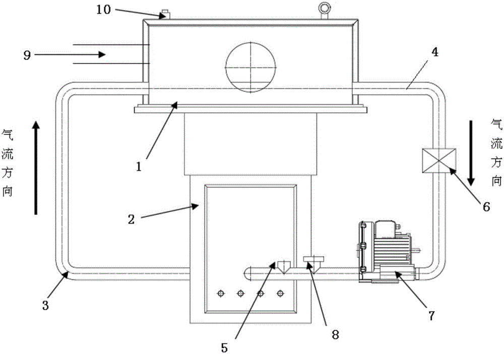
[0038] The present invention provides a laser melting and forming dust removal system with multifunctional circulating air flow, through the internal air circulation design, the air flow flowing into the laser forming working chamber is promoted, refer to Image 6 , to complete at least three main functions, the first is the directional dust removal function of blowing and sucking for the smoke generated by the laser action powder; It is to introduce the airflow into the cavity of the moving slide to produce the effect of discharging dust.

[0039] Specifically, combine figure 1 , the laser melting forming dust removal system with multifunctional circulating air flow includes an upper cavity 1 and a lower cavity 2; the upper cavity 1 is a laser melting forming cavity, and the upper cavity 1 and the lower cavity 2 are connected to each other;

[0040] In addition, the exhaust...


PUM

PropertyMeasurementUnit
heightaaaaaaaaaa

Abstract

The invention provides a laser melting forming dust-removing system with multifunctional circulating air flow and a dust-removing method. The dust-removing system comprises an upper cavity and a lower cavity. Three induced air ways are led out of an air inlet of the upper cavity and are the first induced air way, the second induced air way and the third induced air way. The first induced air way communicates with a dust-removing subsystem in a scanning area. The second induced air way communicates with a dust-removing subsystem of a laser protection mirror. The third induced air way communicates with a dust-removing subsystem of a movement sliding table cavity. The laser melting forming dust-removing system with multifunctional circulating air flow and the dust-removing method have the beneficial effects that in the whole laser melting forming process, smoke-shaped dust generated when lasers act on metal powder can be absorbed into a dust filter in time under the effect of a draught fan, dust generated by part forming is filtered out in time through the dust filter, the influences, on the subsequent forming quality, of the smoke-shaped dust are prevented, and the forming rate is increased; and in addition, the dust is prevented from rising to the position near the laser protection mirror located over the scanning area, and the dust is prevented from entering a sliding table guide rail in the sliding table cavity.

Description

technical field [0001] The invention belongs to the technical field of metal powder laser melting additive manufacturing, and in particular relates to a laser melting forming dust removal system and a dust removal method with multifunctional circulating air flow. Background technique [0002] "3D printing" technology, also known as incremental manufacturing technology, was born in the United States in the 1980s. The development of CAD (computer-aided design), CNC (digital control), automatic control, laser and other technologies is its predecessor. Because it has been developed for less than 30 years. "3D printing" technology is a manufacturing technology that integrates light / mechanical / electricity, computer, numerical control and new materials in the world's advanced manufacturing field. In this field, the technology gap between our country and the developed countries in the world is relatively small, almost on the same starting line. The reason why it is called incremen...

Claims


Application Information

Patent Timeline
Patent Type & Authority Applications(China)
IPC IPC(8): B22F3/105B33Y30/00
CPCY02P10/25
Inventor 林慧敏张爱平柯作伟刘邦涛张佳潘志军全清友
Owner HARBIN FORWEDO MULTI DIMENSIONAL INTELLIGENT EQUIP CO LTD
Why Eureka
Try Eureka