LNG pipeline crossing embankment system and its construction method

A construction method and pipeline technology, applied in the LNG transportation system and its construction field, to achieve the effects of easy control of the construction period, mature construction method and stable structure

Active Publication Date: 2018-04-06
CHINA NAT OFFSHORE OIL CORP +1
View PDF7 Cites 0 Cited by
  • Summary
  • Abstract
  • Description
  • Claims
  • Application Information

AI Technical Summary

Problems solved by technology

At present, there are not many studies on the crossing of LNG pipelines. However, with the continuous development of the LNG industry and the further development of LNG transfer stations and satellite stations along the river and the coast, more and more problems related to the crossing of LNG pipelines will inevitably be involved.

Method used


Image

  • LNG pipeline crossing embankment system and its construction method
  • LNG pipeline crossing embankment system and its construction method
  • LNG pipeline crossing embankment system and its construction method

Examples


Embodiment 1

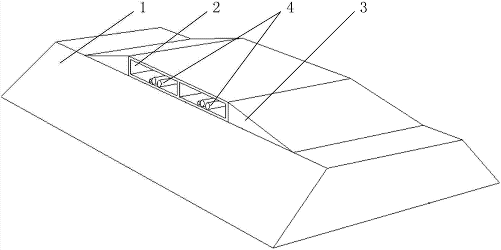
[0049] Such as figure 1 , Figure 4 with Figure 5 As shown, the LNG pipeline embankment system provided in this embodiment includes a dike 1, a box culvert 2, a slope 3, an LNG pipeline 4, an electric heating system 5, a cushion (not shown in the figure) and a waterproof layer 6, wherein , the box culvert 2 is stacked on the top of the dam 1, the slope 3 is set on both sides of the box culvert 2, and the LNG pipeline 4 passes through the dam 1 from the box culvert 2; Between the bottom plates of the box culvert 2, the waterproof layer 6 is arranged outside the box culvert 2.

[0050] In this embodiment, the dam 1 may be an earth dam, a stone dam or a concrete dam.

[0051] In this example, if Image 6 As shown, the LNG pipeline 4 includes an inner pipe wall 41 , a heat insulating layer 42 and an outer pipe wall 43 , wherein the heat insulating layer 42 is made of a cold-insulating material.

[0052] The construction method of the LNG pipeline crossing embankment system o...

Embodiment 2

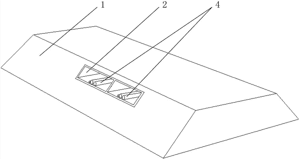
[0065] Such as figure 2 , Figure 4 with Figure 5 As shown, the LNG pipeline embankment system provided in this embodiment includes an embankment 1, a box culvert 2, an LNG pipeline 4, an electric heating system 5, a cushion (not shown in the figure) and a waterproof layer 6, wherein the box culvert 2 is set inside the embankment 1 and passes through the embankment 1, the LNG pipeline 4 passes through the embankment 1 from the box culvert 2, the electric heating system 5 and the cushion are sequentially arranged between the soil inside the embankment 1 and the bottom plate of the box culvert 2, waterproof The layer 6 is arranged outside the box culvert 2 .

[0066] In this embodiment, the dam 1 may be an earthen dam.

[0067] In this example, if Image 6 As shown, the LNG pipeline 4 includes an inner pipe wall 41 , a heat insulating layer 42 and an outer pipe wall 43 , wherein the heat insulating layer 42 is made of a cold-insulating material.

[0068] The construction ...

Embodiment 3

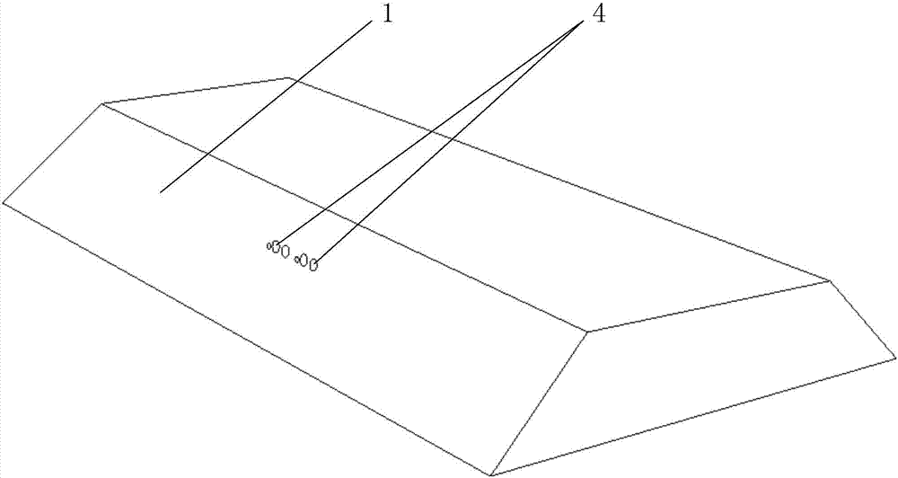
[0081] Such as image 3 with Figure 7 As shown, the LNG pipeline passing system provided in this embodiment includes a dam 1, an LNG pipeline 4 directly passing through the inside of the dam 1, and a waterproof pad 7 wrapping the outside of the LNG pipeline 4; wherein, the dam 1 can be an earthen dam; The LNG pipeline 4 includes an inner pipe wall 41, a heat insulating layer 42 and an outer pipe wall 43, the heat insulating layer 42 is made of a cold insulation material; the waterproof pad 7 can be a concrete layer or a metal material layer, and is used to reduce the water permeability of the LNG pipeline 4 .

[0082] The construction method of the LNG pipeline crossing embankment system of the present embodiment specifically comprises the following steps:

[0083] 1) Testing of the bearing capacity of embankment 1: Estimate the soil bearing capacity of each soil layer of embankment 1 after the construction of the LNG pipeline crossing embankment system. If the estimated so...


PUM


Abstract

The invention relates to systems used for enabling LNG pipelines to cross over a dam and construction methods of the systems, wherein one of the systems used for enabling LNG pipelines to cross over the dam and suitable for a soil, stone-built or concrete dam comprises a box culvert, slopes, LNG pipelines, an electric tracer heating system, a cushion layer and a waterproof layer, wherein the box culvert is stacked at the top of the dam; the slopes are arranged at two sides of the box culvert; the LNG pipelines cross over the box culvert and pass through the dam; the electric tracer heating system is arranged between the top of the dam and a bottom plate of the box culvert; the cushion layer is arranged between the electric tracer heating system and the bottom plate of the box culvert; and the waterproof layer is arranged at the outer side of the box culvert. The other system used for enabling LNG pipelines to cross over the dam and suitable for a soil dam comprises a box culvert, LNG pipelines, an electric tracer heating system, a cushion layer and a waterproof layer, wherein the box culvert is arranged in the dam and passes through the dam; the LNG pipelines cross over the box culvert and pass through the dam; the electric tracer heating system is arranged between a soil body inside the dam and a bottom plate of the box culvert; the cushion layer is arranged between the electric tracer heating system and the bottom plate of the box culvert; and the waterproof layer is arranged at the outer side of the box culvert. The invention also provides another system used for enabling LNG pipelines to cross over the dam and suitable for a soil dam, wherein the system comprises the LNG pipelines directly cross over the inside of the dam and waterproof cushions for wrapping the outer parts of the LNG pipelines.

Description

technical field [0001] The invention relates to an LNG delivery system and a construction method thereof, in particular to an LNG pipeline crossing embankment system and a construction method thereof. Background technique [0002] The main component of liquefied natural gas (LNG, Liquefied Natural Gas) is methane, which is obtained by cooling natural gas to -162°C under normal pressure. The density of liquefied natural gas is about 450kg / m 3 , the volume is about 1 / 600 of the gaseous state. The LNG receiving station is mainly composed of a storage tank area, a dock area, a process area, a gasification area, and a public engineering area. The LNG pipelines between the storage tank area and the dock area must pass through breakwaters. At present, the method of building trestle bridges is usually used to make the LNG pipeline span across the embankment, and the cost of the pipeline is relatively high. In addition, due to the reduction of available shorelines and the lack of ...

Claims


Application Information

Patent Timeline
Patent Type & Authority Patents(China)
IPC IPC(8): F16L7/00F16L53/34F16L53/35F16L59/02
CPCF16L7/00F16L53/35F16L59/021
Inventor 肖立毕晓星彭延建屈长龙张超陈团海段品佳刘永浩刘洋
Owner CHINA NAT OFFSHORE OIL CORP
Why Eureka
Try Eureka